Hardware Aspects of Moving Message Display Project:-
The moving message display is fabricated using these major components:-
1. Micro controller AT89s51
2. LCD
3. RS-232
4. Computer
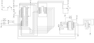
the moving message will be display on the LCD which will be controlled through microcontroller and the message will be sent by computer using RS232. The circuit diagram of the moving message display is shown in this post and how the whole process is completed is discussed here.
The Microcontroller in this software is programmed such that it controls the LCD through an interface. An eight-bit interface between in the LCD and Microcontroller is programmed to transfer the data to be written on the LCD display screen. A further three out pins of the Microcontroller are used to generate control signals for the LCD. The three control signals are generated in the same pattern as discussed in the timing diagram in the previous chapters.
The project, when looked in totality, can be seen as composing of three components, namely LCD, Microcontroller and serial port. The three components have been discussed independently until now and to give a complete picture, it is necessary to link these components. The linking is not only logical but is also translated into hardware connections.
4.1 Serial Port to Microcontroller
The serial port is connected to the Microcontroller to provide the end user with the functionality of passing a desired string to LCD in run time. An interface between the serial port and the Microcontroller is required for the data transfer.
A variable baud rate is generated by the Microcontroller to synchronize the data transfer between the two ends. The connectivity can be analyzed and understood by the hardware diagram at the end of the chapter.
4.2 Microcontroller to LCD
The Microcontroller connects with the LCD with an 8bit interface to for data transfer. Three further pins are required to generate enable, read/write and instruction / data signals for the LCD. These three form a small instruction set that allows different tasks and the functionality provided by the HD44 LCD.
4.2.1 Enable Signal Connection
The enable signal is used as a signal to the LCD by the Microcontroller about the availability of data. A high-to-low edge triggers the LCD into reading its data lines. The data meant for the LCD must be present and latched on the data lines before the enable signal switches from high to logic low. It needs to be understood that data lines for sending instructions and display data are the same, the instruction bits help differentiate among the two for the LCD.
4.2.2 Read/Write Signal Connection
The read/write signal specifies to the LCD whether the Microcontroller is intends to read data from its DDRAM/CGRAM or intends to write data to its DDRAM/CGRAM. In the former case, the data lines contain the data meant for the destination on the LCD memory and in the latter case; the data lines will have the data written onto from the appropriate DDRAM/CGRAM.
4.2.3 Instruction/Data Signal Connection
The instruction/data line specifies whether the data bus contains an instruction or data meant for the LCD. This signal, along with the instruction bits, help LCD in deciding which control signals to generate to fulfill the request.
4.2.4 Busy Flag
After sending of every request, whether instruction or data, to the LCD; the Microcontroller must check for the busy flag of the LCD to return to low logic again. A high logic for the busy flag signals that an internal operation is being carried out and during this time, no external instruction or data is entertained. Only when the busy flag is at a logic low, the Microcontroller should send the next instruction or data. The busy flag is checked by configuring the LCD into read mode (R/W signal is set to logic high) and then reading the data lines. The MSB of the byte read contains the value of the busy flag. To understand the above concepts, the timing diagram mentioned in Chapter 2 for busy flag testing and data transfer may be used.
Tags:-
Hardware Aspects of Moving Message Display Project,LED BASED MOVING DISPLAY USING 8051 ,Scrolling Message in LED Display with 8051,8x8 LED Matrix using 8051 ,A Microcontroller Based Moving Message Display,Project Help / Display Moving Message ,scrolling message display using 8051,LCD and computer PC,Microcontroller Based moving message display,8051 based Moving massage display ,8051 message display, microcontroller moving message display, circuit for moving message display, This is the report of the mini project we did in our sixth semester of Engineering. It uses a at89c51 microcontroller to display 16 messages in moving,moving message display using Lcd and 8051 microcode ,build a moving message display board with 8051 microcontroller,
The moving message display is fabricated using these major components:-
1. Micro controller AT89s51
2. LCD
3. RS-232
4. Computer
the moving message will be display on the LCD which will be controlled through microcontroller and the message will be sent by computer using RS232. The circuit diagram of the moving message display is shown in this post and how the whole process is completed is discussed here.
The Microcontroller in this software is programmed such that it controls the LCD through an interface. An eight-bit interface between in the LCD and Microcontroller is programmed to transfer the data to be written on the LCD display screen. A further three out pins of the Microcontroller are used to generate control signals for the LCD. The three control signals are generated in the same pattern as discussed in the timing diagram in the previous chapters.
The project, when looked in totality, can be seen as composing of three components, namely LCD, Microcontroller and serial port. The three components have been discussed independently until now and to give a complete picture, it is necessary to link these components. The linking is not only logical but is also translated into hardware connections.
4.1 Serial Port to Microcontroller
The serial port is connected to the Microcontroller to provide the end user with the functionality of passing a desired string to LCD in run time. An interface between the serial port and the Microcontroller is required for the data transfer.
A variable baud rate is generated by the Microcontroller to synchronize the data transfer between the two ends. The connectivity can be analyzed and understood by the hardware diagram at the end of the chapter.
4.2 Microcontroller to LCD
The Microcontroller connects with the LCD with an 8bit interface to for data transfer. Three further pins are required to generate enable, read/write and instruction / data signals for the LCD. These three form a small instruction set that allows different tasks and the functionality provided by the HD44 LCD.
4.2.1 Enable Signal Connection
The enable signal is used as a signal to the LCD by the Microcontroller about the availability of data. A high-to-low edge triggers the LCD into reading its data lines. The data meant for the LCD must be present and latched on the data lines before the enable signal switches from high to logic low. It needs to be understood that data lines for sending instructions and display data are the same, the instruction bits help differentiate among the two for the LCD.
4.2.2 Read/Write Signal Connection
The read/write signal specifies to the LCD whether the Microcontroller is intends to read data from its DDRAM/CGRAM or intends to write data to its DDRAM/CGRAM. In the former case, the data lines contain the data meant for the destination on the LCD memory and in the latter case; the data lines will have the data written onto from the appropriate DDRAM/CGRAM.
4.2.3 Instruction/Data Signal Connection
The instruction/data line specifies whether the data bus contains an instruction or data meant for the LCD. This signal, along with the instruction bits, help LCD in deciding which control signals to generate to fulfill the request.

4.2.4 Busy Flag
After sending of every request, whether instruction or data, to the LCD; the Microcontroller must check for the busy flag of the LCD to return to low logic again. A high logic for the busy flag signals that an internal operation is being carried out and during this time, no external instruction or data is entertained. Only when the busy flag is at a logic low, the Microcontroller should send the next instruction or data. The busy flag is checked by configuring the LCD into read mode (R/W signal is set to logic high) and then reading the data lines. The MSB of the byte read contains the value of the busy flag. To understand the above concepts, the timing diagram mentioned in Chapter 2 for busy flag testing and data transfer may be used.
Tags:-
Hardware Aspects of Moving Message Display Project,LED BASED MOVING DISPLAY USING 8051 ,Scrolling Message in LED Display with 8051,8x8 LED Matrix using 8051 ,A Microcontroller Based Moving Message Display,Project Help / Display Moving Message ,scrolling message display using 8051,LCD and computer PC,Microcontroller Based moving message display,8051 based Moving massage display ,8051 message display, microcontroller moving message display, circuit for moving message display, This is the report of the mini project we did in our sixth semester of Engineering. It uses a at89c51 microcontroller to display 16 messages in moving,moving message display using Lcd and 8051 microcode ,build a moving message display board with 8051 microcontroller,


This is the very nice blog about
ReplyDeleteLed moving message display but here are some information if you get more information about led moving message display then visit:
ledtechshop.com
These display is microprocessor based Led Moving Message Display , made up of light emitting diode (LEDs) arranged in an array. The Moving Message or data can be fed & set with the help of keypad on chorded remote provided with this unit. for more information visit: http://www.ledtechshop.com
ReplyDeleteThese display is microprocessor based Moving Message Display, made up of light emitting diode (LEDs) arranged in an array. The Moving Message or data can be fed & set with the help of keypad on chorded remote provided with this unit.for more information visit: http://www.ledtechshop.com
ReplyDelete