Wednesday, March 31, 2010

Schematic Parallel Interface AVR Programmer

Parallel Interface AVR Programmer Project

With this project you can program an AVR microcontroller ATMEL (ATmega8, ATMega32, ...) from a parallel printer LPT1 using ISP functionality In System Programming. This programming type can program and/or configure microcontroller directly on the target board without removing device and put it on a separate programmer. This board is compatible with programming software "PonyProg".

You can check USB AVR Microcontroller Programmer and Simple ISP AVR Programmer for another AVR Programmer project.

Download :
Schematic and Source Code

tag : AVR programmer, Microcontroller Project, Parallel Interface (src)


read more "Schematic Parallel Interface AVR Programmer"

Monday, March 29, 2010

Light Sensor Circuit 1

Tiny Light Sensor With Logic Output Draws Less
Than 10µA

A light-sensing circuit that consumes very little power can
serve as an automatic backlight sensor in portable instruments.
This function is easily implemented with a logic gate or
Schmitt-trigger inverter, but those approaches draw a
considerable amount of supply current.


Figure 1. This light sensor provides a low-to-high output
transition at a light level determined by the value of R1.
more


Sensing Light with a Programmable Gain Amplifier
INTRODUCTION
Photo Sensors bridge the gap between light and electronics.
Microchip’s Programmable Gain Amplifiers
(PGAs) are not well suited for precision applications
(such as CT scanners), but they can be effectively used
in position photo sensing applications minus the headaches
of amplifier stability.


Photo Sensors can be connected directly to Microchip’s PGA.
Based on the level ofluminance to the photo sensor, the gain
of the signal can be changed through the SPI™ port of the
MCP6S26, six-channel PGA.
more pdf

8 Photo-Detector Circuitboards
Visible and Infrared Light
A new version of the 8 Photo-Detector circuitboard where the
Outputs Are LOW When The Inputs Are LOW.
(The LEDs are ON when the Phototransistors are exposed to light.)


more


MAKING A LIGHT / DARK SENSOR
Opposite is a simple light/ dark sensor. This can be connected
as an input or switch to another circuit. The Sensors has three
green wires (1, 2 and 3). Wire 2 should always be connected
to one of the inputs. If wire 1 is also connected then the sensor
acts as a dark sensor. If wires 2 and 3 are connected to the
inputs then sensor operates as a light sensor.


read more "Light Sensor Circuit 1"

Sunday, March 28, 2010

Ultrasonic Sensor Circuit4

40kHz Ultrasonic Driver Circuit for a few pounds

Here is a circuit diagram for an ultrasonic driver circuit suitable
for the the Speed of ultrasound and Lloyd's Mirror using
Ultrasonic Waves experiments. Test the circuit on a plug-in
prototype board to make sure I've transcribed the component
values correctly. I got the circuit to work on a plug-in prototype
board before it was transferred to a printed circuit board (PCB).
The circuit should work with strip board so you shouldn't need
to make a PCB. If somebody does do PCB artwork (or a strip
board layout) they should publish it on the www and I'll link to it.
Many basic electronics books explain the operation of the 555
chip (the 556 chip is a package of two 555 circuits in a single chip).


Ultrasonic Reflectance Detector
This circuit detects motion within approximately 5 inches of
a piezo-ceramic element ultrasonic transducer. The detection
distance is much smaller than obtainable with other ultrasonic
techniques, however, it only requires a single transducer, as
opposed to the two-transducer arrangement typically found in
other designs. The short-range detection is adequate for many
applications, such as proximity-operated commodity dispensers
or tamper alarms for merchandise cases.


Ultrasonic Range Sensor
1 is the connection to the RCX. D1 - D4 form a bridge rectifier
to obtain local power from the RCX which is stored on C7 and
regulated to 5V by U1, a low power, low dropout regulator.
The microcontroller, U3 is programmed to generate a burst of
8 x 40KHz pulses on pin 6. Q1 switches current into L1 creating
a "flyback" voltage output to Y2, the ultrasonic transmitter, of
about 20V peak. The 40KHz is based on a software division of
the 10MHz reference (the ceramic resonator, Y1, in this case).
Y3, the ultrasonic receiver, is band-limited by L2, to stop normal
sound and vehicle vibration from being the dominant input. L2
is chosen to form a resonant circuit with the self capacitance of
the receiver piezo. It should be peaked for 40KHz. U2D and
U2A are the primary gain stages to get the millivolt level signals
up to a couple of volts.


read more "Ultrasonic Sensor Circuit4"

Ultrasonic Sensor Circuit 3

Arduino + Ultrasonic sensor + MP3

In this project for
Martí Guixé we built a small autonomous device
with
Arduino that can detect the presence of people with an
ultrasonic sensor. It then proceeds to play an MP3 song with a
Yampp Industrial II


Ultrasonic range finder uses few components


Measuring distance with ultrasonic signals requires a transmitting
ultrasonic transducer; a medium, such as air or water; a reflecting
surface or object; a receiving ultrasonic transducer; and a
time-of-flight measurement circuit. The speed of sound in air at
20 C is approximately 343m/sec, which translates to about 1 in. Per
74 Wsec. Doubling the time gives you the round-trip speed, which
is 1 in. per 148 Wsec. Four aspects of the system limit the
maximum measurable distance: the amplitude of the sound wave,
the texture of the reflecting surface, the angle of the surface with
respect to the incident sound wave, and the sensitivity of the
receiving transducer. The receiving transducer's direct reception
of the sonar pulse—and not the echo—usually dictates the
minimum measurable distance.


Circuit drawingfor Ultrasonic Range Meter


read more "Ultrasonic Sensor Circuit 3"

Wednesday, March 24, 2010

Schematic Robot Project : Nickel-O-Matic

electronic robotic project

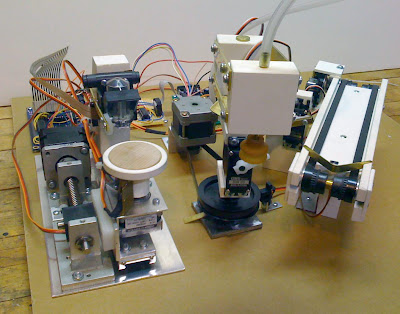
Nickel-O-Matic was designed to entertain and provides gratuitous mechanical motion rather than efficient production. Nickel-O-Matic uses inkjet technology to print a custom message on both sides of 1-1/2" diameter blank wooden nickels. The robot uses a BASIC Stamp 2 to control much of the mechanical movement and a Propeller Chip to control the Inkjet system. The two controllers run a total of four hobby servos, three stepper motors, one DC motor, one DC vacuum pump, one inkjet head, and five IR sensors.

Mike Davey, the designer, said that the system was built as a number of modules to make design and trouble shooting simpler. The most complex of the modules is the inkjet system. At the center of the inkjet module is a spindle that rotates the wooden nickel under the inkjet head. This spindle is turned with a stepper motor and allows for repeatable placement of the nickel under the inkjet head. The spindle is also moved horizontally under the inkjet head by a second stepper motor coupled to a lead screw and slide mechanism. A Propeller Chip controls all the elements of the inkjet module. The Propeller Chip was chosen for the inkjet system for two reasons. The first is that the inkjet required fast and accurate timing. The Propeller Chip has direct control over the inkjet head through a simple Darlington transistor array. Each of the inkjet's 12 nozzles needs pulsed on for no more than 6 microseconds. The second reason the Propeller Chip was chosen is that the module needed at least 24 IO pins to control the inkjet module. The inkjet head needs 12 pins, the two steppers need 4 pins each, there are three IR sensors, and I needed at least one pin to communicate with the BASIC Stamp 2.

Download :


Source code

tags : robotic, propeller, project, electronic src


read more "Schematic Robot Project : Nickel-O-Matic"

Control Checking the maintenance and reparation of the PLC and making the report

Testing the PLC
After the PLC is repaired then do the testing by operating the PLC as according to procedure. Perceive and check, whether the PLC run normally or there is still error which emerge. If there is still error, reenact the reparation step.


Example of the Omron PLC test run procedure;
Power Supply Application
  • Check the PLC’s power supply voltage and terminal connections.
  • Check the I/O devices’ power supply voltage and terminal connections.
  • Turn on the power supply and check that the “PWR” indicator lights.
  • Use a Programming Device to set the PLC to PROGRAM mode.
I/O Wiring Checks
  • With the PLC in PROGRAM mode, check the output wiring by turning on the output bits with the force set and force reset operations.
  • Check the input wiring with the PLC’s input indicators or a Programming Device’s monitor operations.
Test Run
  • Use a Programming Device to set the PLC to RUN or MONITOR mode and check that the “RUN” indicator lights.
  • Check the sequence of operation with the force set/reset operations, etc.

Debugging
Correct any programming errors that are detected.

Saving the Program
  • Use a Programming Device to write the program to a backup floppy disk.
  • Print out a hard copy of the program with a printer.

Making the report
The report is made for documentation. Documentation of the PLC maintenance represent the equipment of maintenance administration to help the fluency of the next maintenance. With the good documentation and depository of the good administration peripheral, we will be more easy to look for the archives nor things which we need.
Documentation of the PLC maintenance usually consisted of the following matters;
  • Installation guide
  • Operation manual
  • Maintenance manual
  • Sparepart list
  • Sheet of component data
  • Layout diagram
  • Troubleshooting Questionnaire
  • Number phone of the service center
  • Last Maintenance Record or last maintenance report
  • Print out or hard copy from program listing
  • Back-up program
Example of The troubleshooting questionnaire on the LG PLC.

read more "Control Checking the maintenance and reparation of the PLC and making the report"

Tuesday, March 23, 2010

Control Maintenance and reparation the PLC

This section explains matters that must be known in maintenance and reparation the PLC.


Applying the safety procedure
During execution of the work, the safety procedure must be executed truly so that the risk of the work accident can be avoided.
Example of applying the safety procedure;
  • Use the safety equipment
  • Follow the instruction of safety procedure
  • Comprehending fringe of writing on the wall or emergency

Checking the installation and power supply
To do the maintenance and reparation of the PLC system, one of the important matter that must be done is perform the inspection to the PLC installation as according to the manual instruction, for example;


Maintain and repair the PLC
The maintenance and reparation of the PLC is all activity which intentionally be done to the PLC by following a systematic procedure with target so that the PLC which we own always can be used in the best condition, fluent, peaceful and technically has along live.

Preventive maintenance
The main system components of a PLC system are semiconductors, and it contains few components with limited lifetimes. Poor environmental conditions, however, can lead to deterioration of the electrical components, making regular maintenance necessary. The standard period for maintenance checks is 6 months to 1 year, but more frequent checks are required if the PLC is operated in more demanding conditions. When inspecting one or two times per six months, check the following items.


Preventive maintenance consisted of several activity below;

Pre maintenance
Pre maintenance is a preparation activity, matters which require to be prepared for example;
  • Prepare the maintenance equipment
  • Prepare the maintenance material especially weared routinely, for example; cleanser material, Iubricant material, corrosion preventative material, etc.
  • Prepare the maintenance documentation
  • Prepare the power supply and air compressor

Daily maintenance
The following table shows the inspection and items which are to be checked daily.


Periodic maintenance
Check the following items once or twice every six months, and perform the needed corrective actions.


Several example of the maintenance activity on the Omron PLC is shown below;
CPU and Power Supply Fuses


To replace a fuse, follow the steps below:
  • Turn OFF the power to the PLC.
  • Remove the fuse holder by turning it approximately 50? counterclockwise with a standard screwdriver.
  • Remove the fuse from the holder.
  • Insert a new fuse.
  • Reattach the fuse holder by turning it approximately 50? clockwise with a standard screwdriver.

Output Unit Fuses
To replace a fuse, follow the steps below. Use only UL/CSA certified replacement
fuses.


  • Turn OFF the power to the PLC.
  • Detach the terminal block by unlocking the lock levers at the top and bottom of the terminal block.
  • While pushing down the lock lever on the Backplane with a screwdriver as shown below, remove the Output Unit.

  • Remove the screw from the top of the Unit (Phillips screwdriver).
  • Detach the case from the Unit (flat-blade screwdriver).

  • Pull out the printed circuit board.
  • Insert a new fuse. A spare fuse is provided inside the rear of the case when the Unit is delivered.
  • Reassemble in reverse order of assembly.

Output Unit Relays
To replace a Relay, follow the steps below:
  • Turn OFF the power to the PLC.
  • Detach the terminal block by unlocking the lock levers at the top and bottom of the terminal block.
  • While pushing down the lock lever on the Backplane with a screwdriver as shown below, remove the Output Unit.


  • Remove the screw from the top of the Unit (Phillips screwdriver).
  • Detach the case from the Unit (flat-blade screwdriver).

  • Pull out the printed circuit board. The Relays are placed on the PLC boards of individual Units as shown in the figures below.

  • A Relay puller is provided inside the rear of the case when the Unit is delivered. Use the Relay puller to pull out the Relay as shown below. Insert a new Relay.

  • Reassemble in reverse order of assembly.

Batteries
Some RAM Packs use a battery. When the battery is nearly discharged, the ALARM indicator blinks and the message “BATT FAIL” appears on the Programming Console. When this occurs, replace the battery within one week to avoid loss of data. The battery comes together with its connector as a set. To replace the Battery Set, follow the steps below. The entire replacement must be completed within five minutes to ensure that the
data will not be lost.
If you are using model C200H-CPU11-E as the CPU, the battery is installed in the Unit upon delivery.
  • Turn OFF the power to the PLC. (If the power was not already ON, turn the power ON for at least one minute before turning the power OFF.)
  • Remove the cover from the battery compartment of the RAM Pack.
  • Remove the old Battery Set.
  • Install the new Battery Set as shown shown in the following diagram.


  • Replace the cover of the battery compartment.
  • Press CLR, FUN, MONTR, MONTR or just turn the power to the PC OFF and then ON again to clear the error message on the Programming Console.


Reparation
Reparation is an activity which consist of troubleshooting, analysis or diagnosis and corrective actions. The following explains contents troubleshooting, diagnosis and corrective actions for various errors that can occur during system operation.

Basic Procedures of Troubleshooting
System reliability not only depends on reliable equipment but also on short down times in the event of faults. The short discovery and corrective action is needed for speedy operation of system.

The following shows the basic instructions for troubleshooting.
Visual checks
Check the following points.
  1. Machine operating condition (in stop and operating status)
  2. Power On/Off
  • Status of I/O devices
  • Condition of wiring (I/O wires, extension and communications cables)
  • Display states of various indicators (such as POWER LED, RUN LED, ERR. LED and I/O LED).
After checking them, connect peripheral devices and check the operation status of the PLC and the program contents. Use the error code list to determine the happening error.

Trouble Check
Observe any change in the error conditions during the following.
  • Switch to the STOP position, and then turn the power on and off.

Narrow down the possible causes of the trouble where the fault lies, i.e.:

  • Inside or outside of the PLC?
  • I/O module or another module?
  • PLC program?


Troubleshooting
The following example explains the procedure for determining the cause of troubles as well as the errors and corrective actions to the LG PLC.


Troubleshooting flowchart used when the POWER LED turns OFF
The following flowchart explains corrective action procedure used when the power is supplied or the power led turns off during operation.


Troubleshooting flowchart used when the ERR LED is flickering
The following flowchart explains corrective action procedure use when the power is supplied starts or the ERR LED is flickering during operation.


Troubleshooting flowchart used when the RUN LED turns off
The following flowchart explains corrective action procedure to treat the lights-out of RUN LED when the power is supplied, operation starts or operation is in the process.


Troubleshooting flowchart used when the I/O part doesn’t operate normally
The following flowchart explains corrective action procedure used when the I/O module doesn’t operate normally.


Troubleshooting flowchart used when a program cannot be written to the CPU
The following flowchart shows the corrective action procedure used when a program cannot be written to the PLC module.


The following example explains the procedure for determining the cause of troubles as well as the errors and corrective actions to the Omron PLC. Use the following flowcharts to troubleshoot errors that occur during operation.

Main Check


Power Supply Check


Fatal Error Check


Non-fatal Error Check


I/O Check
The I/O check flowchart is based on the following ladder diagram section.


Environmental Conditions Check


Memory Error Check


Troubleshooting Examples on the PLC electronic circuit
Possible troubles with various circuits and their corrective actions are explained.
Input circuit troubles and corrective actions
The followings describe possible troubles with input circuits, as well as corrective actions.


Output circuit troubles and corrective actions
The following describes possible troubles with input circuits, as well as their corrective actions.


Output circuit troubles and corrective actions (continued).


Error code list
The following example shows error code list on the LG PLC.

continued;
read more "Control Maintenance and reparation the PLC"

Control Planning and preparing the work to maintain and repair the PLC

Planning is basic function of management. So that the risk could be minimized, with that all the work, action and policy must be planned beforehand. While preparation represent the follow-up from planning, where in preparation all material and equipment required to be collected and checked before the work is executed. Planning and preparation gives the complete and clear representation about all the work.


Matters which require to be planned and prepared for example;

Compiling the work plan

Compiling the work plan is an activity to make the sequence of the most efficient work execution steps. In compiling the work plan is given high priority to the parts of easy done beforehand, then difficult shares.

Under given some guidance can be used;

Preventive maintenance
  • Pre maintenance
  • Daily maintenance
  • Periodic maintenance
Reparation
  • Troubleshooting
  • Reparation analysis/diagnosis
  • Execution of reparation
  • Testing the result of reparation
Maintenance administration
  • Documentation the result of maintenance
  • Depository the administration peripheral
  • Depository the material
  • Depository the result of reparation

Checking the wiring diagram
This phase is important enough because by checking the wiring diagram and learn it, people can immediately comprehend the work principle of the PLC that will be diagnosed its damage.
A simple wiring diagram of the PLC is shown below;


Preparing tools, materials and safety equipments
Tools and materials required to be collected and then checked one by one to ensure that the equipments and materials in good condition and can be used.
Materials required;
  • Cable
  • I/O devices
Standard Tools (Required);
  • Screwdrivers (Phillips and flat-blade) / tools set
  • Voltage tester or digital voltage meter
  • Industrial alcohol and a cotton cloth
  • Safety equipment
  • Programming device
Measurement Devices (May be Needed);
  • Synchroscope
  • Cathode-ray oscilloscope
  • Thermometer
  • hygrometer


Coordinating the work
After the work plan is compiled, team member concerned in completion of the task is contacted to ensure that the work has been coordinated effectively so that is not happened the misunderstanding at the time of work execution.


Safety Procedure
Safety Procedure is a prevention action so that is not happened the accident at the time of work excecution that may be happened to the worker or other people, machine, equipment and environmental in any time and any where.
The safety equipment for example:
  • Wear
  • Safety shoes
  • Helmet Gloves
  • Safety glasses
  • Masker, etc

Prevention of the happening of accident in the work place must pay attention some factors for example :
  • Ascertaining equipments in good condition
  • Ascertaining wear in good condition
  • Must discipline in using the equipment
  • Must attentive and concentration at the work
  • Ascertaining has comprehended the way of operation of the machine or equipment
  • Ascertaining body condition before working in good health
read more "Control Planning and preparing the work to maintain and repair the PLC"

Control Introduction

My article in this time explains how to maintain and repair a Programmable Logic Controller (PLC). This article I compile in 3 titles. To see the picture on this article more detail, you can access on the picture.

Title 1 : Planning and preparing the work to maintain and repair the PLC
Explains about the matters that must be planned and prepared before maintain and repair the PLC.

Title 2 : Maintenance and reparation the PLC
Explains about the matters that must be known before maintain and repair the PLC.

Title 3 : Checking the work and making the report
Explains abouts checking the maintenance and reparation of the PLC and making the report.


Reference;

  • Installation guide of the Omron PLC
  • Troubleshooting guide of the LG PLC
  • Maintenance manual of the LG PLC
  • "PLC Maintenance & Reparation" ; Training module of Department of Labour and Transmigration of Indonesia


read more "Control Introduction"

Monday, March 15, 2010

Schematic Cheap AVR I2C Tiny Usb

Cheap AVR I2C Tiny Usb

I2c-tiny-usb made to provide a cheap generic i2c interface to be attached to the usb. It could be as simple and cheap printer port to i2c adapters. A USB solution has several advantages such as the built-in power supply and no cpu intense bitbanging is required on the host side. This USB solution even requires less parts than some printer port solutions. Although i2c-tiny-usb was developed under and for Linux but it also works under Windows and MacOS X.

The hardware the i2c-tiny-usb interface which is designed by Till Harbaumof consists of the Atmel AVR ATtiny45 CPU, a cheap and easy to obtain microcontroller with 4 KBytes flash (of which ~2k are used in this application) and 256 Bytes RAM. And few other parts surrounded the processor.

Download :
Source code, schematic and documentation

tag : USB project, i2c adapter, printer port adapter, avr project (src)


read more "Schematic Cheap AVR I2C Tiny Usb"