Tuesday, August 23, 2011

Schematic Arduino Line Following Robot

arduino robot line follower
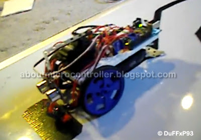
The project goal is to build a line follower robot that can follow a dark like, on a light background. It uses an Arduino Duemillanove with the AVR ATMega 328 as main processor. For driving force the project equipped with two Parallax Futaba Continuous Rotation Servos. The robot sensor uses Pololu QTR-6A IR Reflectance Sensor Array. The system powered by 4 rechargeable NiMH Duracell AA Batteries.

 "It first calibrates itself for 5 seconds. You move it across the line a few times so it gets used to the difference in reflectance. After the calibration it begins moving forward", said DuFFxP93, the designer.

read more "Schematic Arduino Line Following Robot"

2 wheel robot turns

Robot wheels have very little, if any, sideways motion
(assuming that the center of gravity of the robot is close
to the two wheels). The circle in the front of the robot is
a skid of some soft (this is any smooth piece of plastic,
such as a ping-pong ball or a bottle cap). Because this
skid is smooth, it doesn’t mind making the large sideways
motion, and the robot will turn easily.


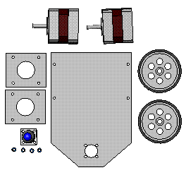
We use two step motor and one ping-pong ball
robot part

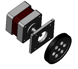
Assembly motor and wheel

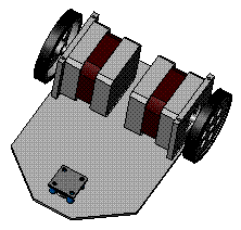
Put them to Base plate

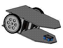
Close by top plate


Idea of 4 wheel robot 1

read more "2 wheel robot turns"

Monday, August 22, 2011

Control Dynamic Analyze of Snake Robot

A Dynamic Single Actuator Vertical Climbing Robot
Abstract—A climbing robot mechanism is introduced, whichuses dynamic movements to climb between two parallel verticalwalls. This robot relies on its own internal dynamic motionsto gain height, unlike previous mechanisms which are quasistatic.One benefit of dynamics is that it allows climbingwith only a single actuated degree of freedom. We showwith analysis, simulations and experiments that this dynamicrobot is capable of climbing vertically between parallel walls.We introduce simplifications that enable us to obtain closedform approximations of the robot motion. Furthermore, thisprovides us with some design considerations and insights intothe mechanism’s ability to climb.

http://www.cs.cmu.edu/~biorobotics/papers/IROS07_Degani_0490.pdf

3-D Snake Robot Motion: Nonsmooth Modeling,Simulations, and Experiments
Abstract—A nonsmooth (hybrid) 3-D mathematical model ofa snake robot (without wheels) is developed and experimentallyvalidated in this paper. The model is based on the framework ofnonsmooth dynamics and convex analysis that allows us to easilyand systematically incorporate unilateral contact forces (i.e., betweenthe snake robot and the ground surface) and friction forcesbased on Coulomb’s law of dry friction. Conventional numericalsolvers cannot be employed directly due to set-valued force lawsand possible instantaneous velocity changes. Therefore, we showhow to implement the model for numerical treatment with a numericalintegrator called the time-stepping method. This methodhelps to avoid explicit changes between equations during simulationeven though the system is hybrid. Simulation results for theserpentine motion pattern lateral undulation and sidewinding arepresented. In addition, experiments are performed with the snakerobot “Aiko” for locomotion by lateral undulation and sidewinding,both with isotropic friction. For these cases, back-to-back comparisonsbetween numerical results and experimental results are given.


http://www.zfm.ethz.ch/~leine/papers/Transeth%20&%20Leine%20&%20Glocker%20&%20Pettersen%20-%203-D%20Snake%20Robot%20motion%20nonsmooth%20modeling%20simulations%20and%20experiments.pdf


Dynamic Analyze of Snake Robot
Abstract—Crawling movement as a motive mode seen in natureof some animals such as snakes possesses a specific syntactic anddynamic analysis. Serpentine robot designed by inspiration fromnature and snake’s crawling motion, is regarded as a crawling robot.In this paper, a serpentine robot with spiral motion model will beanalyzed. The purpose of this analysis is to calculate the vertical andtangential forces along snake’s body and to determine the parametersaffecting on these forces. Two types of serpentine robots have beendesigned in order to examine the achieved relations explained below.


http://www.waset.org/journals/waset/v29/v29-56.pdf
http://water.engr.psu.edu/reed/Education/CE%20563%20Projects/Mehta%20snakebot_nsga2%20%20Sp%2007.pdf

Optimal Gait Analysis of Snake Robot Dynamics
ABSTRACT
Though there have been a lot of research in the area ofsnake-robot kinematics and dynamics, a little attention hasbeen given to ¯nd out an optimal gait for the robot. Thisoptimal gait until now is being calculated using a graphicalmethod. An attempt, here, is made to get these optimumgait parameters using evolutionary algorithms.We intend to optimize the input power consumed by therobot for a given propulsive speed. A popular multi-objectiveevolutionary algorithm developed by Deb et al., NSGA-II isused in this work and the results are presented.Results from an approximation of objective function throughpolynomials and from the actual simulation are presented.Two di®erent frictional models are considered and their re-sults are given. The results are in good agreement with theliterature. A parametric study is also included to ¯nd min-imum population size and number of generations. The per-formance metrics are used to justify the parametrization.


AmphiBot I: an amphibious snake-like robot
Abstract
This article presents a project that aims at constructing a biologically inspired amphibious snake-like robot. The robot isdesigned to be capable of anguilliform swimming like sea-snakes and lampreys in water and lateral undulatory locomotionlike a snake on ground. Both the structure and the controller of the robot are inspired by elongate vertebrates. In particular, thelocomotion of the robot is controlled by a central pattern generator (a system of coupled oscillators) that produces travellingwavesof oscillations as limit cycle behavior. We present the design considerations behind the robot and its controller. Experimentsare carried out to identify the types of travelling waves that optimize speed during lateral undulatory locomotion on ground. Inparticular, the optimal frequency, amplitude and wavelength are thus identified when the robot is crawling on a particular surface.


http://birg2.epfl.ch/publications/fulltext/crespi05.pdf


Analysis and Design of A Multi-Link Mobile Robot (Serpentine)
Abstract
This paper is a study on dynamic behavior of a :snakerobot, called Serpentine robot, 2”* version (SR#2). TheSR#2 is the latest version of snake robots developed atFIBO as a research platform for studying serpmtinegaits. The gait is in form of sinusoidal curve, consi,deredone of the most effectiveness crawling pattem i:n thenatural world. The Active Cord Mechanism (ACM)assumption, initiated by Hirose, is implemented. Therobot motion results from different joint torquer, andfrictional reacting forces in each wheel. In this stud:y, weproposed a modified serpeniod function with steeringcommand to control the robot’s direction. We alsoperformed dynamic analysis using Kane’s method.Holonomic constraints under frictional forces andnonholonomic constraints unders velocities wereconsidered. We verified our algorithm .for directionalcontrol on this Serpentine robot both simulation andexperiment.


http://gicl.cs.drexel.edu/wiki-data/images/f/fc/AnalysisAndDesignOfAMulti-LinkMobileRobot(Serpentine).pdf
read more "Control Dynamic Analyze of Snake Robot"

Friday, August 19, 2011

Control PLC Programming

Programming Languages
A program loaded into PLC systems in machine code, a sequence of binary code numbers to represent the program instructions.Assembly language based on the use of mnemonics can be used, and a computer program called an assembler is used to translate the mnemonics into machine code.High level Languages (C, BASIC, etc.) can be used.

Programming Devices
PLC can be reprogrammed through an appropriate programming device:

[1]Programming Console
[2]PC
[3]Hand Programmer
Introduction to Ladder Logic
Ladder logic uses graphic symbols similar to relay schematic circuit diagrams.Ladder diagram consists of two vertical lines representing the power rails. Circuits are connected as horizontal lines between these two verticals.

Ladder diagram features
Power flows from left to right.
Output on right side can not be connected directly with left side.
Contact can not be placed on the right of output.
Each rung contains one output at least.
Each output can be used only once in the program.
A particular input a/o output can appear in more than one rung of a ladder.
The inputs a/o outputs are all identified by their addresses, the notation used depending on the PLC manufacturer.


Introduction to Statement list
Statement list is a programming language using mnemonic abbreviations of Booleanlogic operations. Boolean operations work on combinationof variables that are true or false.A statement is an instruction or directive for the PLC.

Statement List Operations


  • Load (LD) instruction.
  • And (A) instruction.
  • Or (O) instruction.
  • Output (=) instruction.

Function Block DiagramsFunction block is represented as a box with the function name written in.

please note: LD: load
O: or
AN: and not (and a normally closed contact)
ALD: AND the first LD with second LD


read more "Control PLC Programming"

Control PLC Communications

Extension modules
PLC I/O number can be increased through certain additional modules by system extension through extension lines. Each module can contain extension both of input and output lines.
Extension modules can have inputs and outputs of a different nature from those on the PLC controller. When there are many I/O located considerable distances away from the PLC an economic solution is to use I/O modules and use cables to connect these, over the long distances, to the PLC.

Remote I/O connections
When there are many I/O located considerable distances away fromthe PLC an economic solution is to use I/O modules and use cables toconnect these, over the long distances, to the PLC.

Remote PLCs
In some situations a number of PLCs may be linked together with a master PLC unit sending and receiving I/O data from the other units.

Cables
Twisted-pair cabling, often routed through steel conduit. Coaxial cable enables higher data rates to be transmitted and does not require the shielding of steel conduit.Fiber-optic cabling has the advantage of resistance to noise, small size and flexibility.

Parallel communication
Parallel communication is when all the constituent bits of a word aresimultaneously transmitted along parallel cables. This allows data to be transmitted over short distances at high speeds. Might be used when connecting laboratory instruments to the system.

Parallel standards
The standard interface most commonly used for parallel communication is IEEE-488, and now termed as General Purpose Instrument Bus (GPIB).Parallel data communications can take place between listeners , talkers , and controllers.
There are 24 lines: 8 data (bidirectional), 5status & control, 3 handshaking, and 8 ground lines.

Serial communication
Serial communication is when data is transmitted one bit at a time. A data word has to be separated into its constituent bits for transmission and then reassembled into the word when received. Serial communication is used for transmitting data over long distances. Might be used for the connection between a computer and a PLC.

Serial standards
RS-232 communications is the most popular method of plc to external device communications. RS 232 is a communication interface includedunder SCADA applications. Other standards such as RS422 and RS423are similar to RS232 although they permit higher transmission rates and longer cable distances.

There are 2 types of RS-232 devices:
DTE - Data Terminal Equipment and a common example is a computer.
DCE - Data Communications Equipment and a common example is a modem.
PLC may be either a DTE or DCE device.

ASCII
ASCII is a human-readable to computer-readable translation code(each letter/number is translated to 1’s and 0’s). It’s a 7-bit code, so we can translate 128 characters (2^7 is 128).

Protocols
It is necessary to exercise control of the flow of data between two devices so what constitutes the message, and how the communication is to be initiated and terminated, is defined.
This is termed the protocol.One device needs to indicate to the other to start or stop sending data.Interconnecting several devices can present problems because of compatibility problems.
In order to facilitate communications between different devices the International Standard Organization (ISO) in 1979 devised a model to be used for standardization for Open System Interconnection (OSI).
read more "Control PLC Communications"

Control PLC Operation

Input Relays
These are connected to the outside world. They physically exist and receive signals from switches, sensors, etc. Typically they are not relays but rather they are transistors.

Internal Utility Relays
These do not receive signals from the outside world nor do they physically exist. They are simulated relays and are what enables a PLC to eliminate external relays.There are also some special relays that are dedicated to performing onlyone task.

Counters
These do not physically exist. They are simulated counters and they can be programmed to count pulses.Typically these counters can count up, down or both up and down. Since they are simulated they are limited in their counting speed.Some manufacturers also include highspeed counters that are hardware based.

Timers
These also do not physically exist. They come in many varieties and increments.The most common type is an on-delay type.Others include off-delay and both retentive and non-retentive types. Increments vary from 1ms through 1s.

Output Relays
These are connected to the outside world. They physically exist and send on/off signals to solenoids, lights, etc.They can be transistors, relays, or triacs depending upon the model chosen.

Data Storage
Typically there are registers assigned to simply store data. Usually used as temporary storage for math or data manipulation.They can also typically be used to store data when power is removed from thePLC.
read more "Control PLC Operation"

Control PLC Hardware

Hardware Components of a PLC System


Processor unit (CPU),
Memory,
Input/Output,
Power supply unit,
Programming device,
other devices.

Central Processing Unit (CPU)

CPU - Microprocessor based, may allow arithmetic operations, logic operators, block memory moves, computer interface, local area network, functions, etc.CPU makes a great number of check-ups of the PLC controller itself so eventual errors would be discovered early.


System Busses

The internal paths along which the digital signals flow within the PLC are calledbusses.


The system has four busses:
  • The CPU uses the data bus for sending data between the different elements,

  • The address bus to send the addresses of locations for accessing stored data,

  • The control bus for signals relating to internal control actions,

  • The system bus is used for communications between the I/O ports and the I/O unit.
Memory
System (ROM) to give permanent storage for the operating system and the fixed data used by the CPU.
RAM for data. This is where information is stored on the status of input and output devices and the values of timers and counters and other internal devices. EPROM for ROM’s that can be programmed and then the program made permanent.

I/O Sections
Inputs monitor field devices, such as switches and sensors.
Outputs control other devices, such as motors, pumps, solenoid valves, and lights.

Power Supply
Most PLC controllers work either at 24 VDC or 220 VAC.
Some PLC controllers have electrical supply as a separate module, while small and medium series already contain the supply module.

Programming Device
The programming device is used to enter the required program into the memory of the processor.The program is developed in the programming device and then transferred to the memory unit of the PLC.
read more "Control PLC Hardware"