Showing posts with label Robot Sensor. Show all posts

Tuesday, July 27, 2010

Compass Sensor with Microcontroller Project


INTERFACING AN ANALOG COMPASS TO AN EMBEDDEDCONTROLLER
AbstractThis paper describes the development of a compass sensing unit for use on a remotely operated vessel. The sensor determines the direction of the vessel’s path to aide the user in operating the boat wirelessly through a laptop. The system provides information tofacilitate tracking and controlling the boat when it is not easily seen by the operator. The selected compass, Dinsmore R1655 analog compass sensor, was used in conjunction ofan 8051 microcontroller to provide the necessary data. The system was able to read an analog value from the sensor and convert it to digital direction. The paper will describe the system design and present test results.


http://www.icee.usm.edu/icee/conferences/asee2007/
papers/630_INTERFACING_AN_ANALOG_COMPASS_TO_AN_EMBE.pdf

Microcontroller Design Final Project: Digital Compass
The goal of this project is to build a digital compass that displays both the direction and cardinal points on a television. Other functionalities were added to complement the sensor interface, such as, temperature display, magnetic declination input and disability option.


http://instruct1.cit.cornell.edu/courses/ee476/FinalProjects/s2004/ccw27/index.htm

Electronic Compass Design using KMZ51 and KMZ52
This paper describes how to realize electronic compass systems using the magnetoresistive Sensors KMZ51 and KMZ52 from Philips Semiconductors. Therefore, firstly an introduction to the characteristics of the earth´s magnetic field is given. In the following, the main building blocks of an electronic compass are shown, which are two sensor elements for measuring the x- and y-components of the earth field in the horizontal plane, a signalconditioning unit and a direction determination unit.

Functional block diagram of an electronic compass


http://www.nxp.com/acrobat_download/applicationnotes/AN00022_COMPASS.pdf


Autocalibration of an Electronic Compass for Augmented Reality
Abstract
Electronic compass is often used to provide the absoluteheading reference for tracking the user’s head and handsin Virtual Reality (VR) and Augmented Reality (AR),especially for outdoor AR applications. However,compass is vulnerable to environment magnetismdisturbance. Existing compass calibration methodsrequire complex steps and true heading reference whichis often impossible to be obtained in outdoor ARapplications, and is useful only when compass is inhorizontal plane. An autocalibration method without theneed of heading reference and redundant Sensors isproposed in this paper. First the compass error modelbased on physical principle is presented, then thealgorithm to calculate the compensation coefficients witha set of sample measurements of the Sensors in thecompass is described. Because the influence of theenvironmental disturbance has been effectivelycompensated, the calibrated compass can providedaccurate heading even when it is under large tilt attitude.

http://csdl2.computer.org/comp/proceedings/ismar/2005/2459/00/24590182.pdf


3-AXIS COMPASS REFERENCE DESIGN with Microcontroller Circuit


The HMC1052 two-axis magnetic sensor contains two Anisotropic Magneto-Resistive (AMR) sensor elements in a singleMSOP-10 package. Each element is a full wheatstone bridge sensor that varies the resistance of the bridge magnetoresistorsin proportion to the vector magnetic field component on its sensitive axis. The two bridges on the HMC1052 areorientated orthogonal to each other so that a two-dimensional representation of an magnetic field can be measured. Thebridges have a common positive bridge power supply connection (Vb); and with all the bridge ground connections tiedtogether, form the complete two-axis magnetic sensor. Each bridge has about an 1100-ohm load resistance, so eachbridge will draw several milli-amperes of current from typical digital power supplies. The bridge output pins will present adifferential output voltage in proportion to the exposed magnetic field strength and the amount of voltage supply acrossthe bridge. Because the total earth’s magnetic field strengthis very small (~0.6 gauss), each bridge’s vector component ofthe earth’s field will even be smaller and yield only a couple milli-volts with nominal bridge supply values. Aninstrumentation amplifier circuit; to interface with the differential bridge outputs, and to amplify the sensor signal byhundreds of times, will then follow each bridge voltage output.

http://www.ssec.honeywell.com/magnetic/datasheets/hmc1055.pdf
read more "Compass Sensor with Microcontroller Project"

Sunday, April 18, 2010

Infrared Distance Sensor with the Microcontroller Project


Infrared and Ultrasonic Scanner
(ATMEGA32 microcontroller)


This project is a short range, infrared and ultrasonic
scanner that uses a standard hobby servo to move the
Sensors and a color LCD screen to display the information
from the distance Sensors . The information displayed
on the LCD is an overhead view of the scanning area,
with increments of distance from the distance Sensors .


Hardware Details:
The core of the project is the ATMEGA32 microcontroller
from Atmel. It controls the servo, gathers information from
the Sensors and places the information on the LCD screen.
There is 32K of flash in the microcontroller and the software
uses about 13K of that. Since the LCD uses a maximum of
3.3V, the microcontroller is run at 3.3V.
More


Interfacing the GP2D02 to a Microcontroller PIC and
Sweeping it with a Hobby Servo


The Sharp GP2D02 is a sensitive compact distance measuring
sensor. It required two lines from a microcontroller in order to be
controlled. One line provides the signal to begin a measurement
and also is used to provide a clock signal when transmitting the
distance measure, and the other line is used to transmit the
measurements back to the microcontroller. I interfaced the GP2D02
to a 12CE519 microcontroller rather than my main CPU (16C77) in
order to free up processing time on the 16C77. The GP2D02 requires
an open collector on its input line, so I connected it through a diode
to the 12CE519. The GP2D02 output is connected directly to the
12CE519. As I was limited to one GP2D02 IR sensor per robot,
I used a hobby servo motor to sweep the GP2D02 through a 50
degree pattern in the front of the robot. The servo used was a
Cirrus CS-70 Standard Pro Servo.


more


The MBasic Compiler - DISTANCE Sensors
TYPES OF DISTANCE MEASURING DEVICES

There are many different types of technologies and devices
used in measuring distance, some of them being: Radar, Sonar,
Laser, Infrared and Ultrasonic. In this chapter Infrared and
Ultrasonic will be covered. Infrared uses light that is invisible to
the human eye. Also Infrared light bounces off almost everything.
Its main disadvantage is that fluorescent lights generate it and that
can cause interference. Ultrasonic uses sound that is inaudible to
the human ear. Its main advantage is that it is not sensitive to objects
of different colors and light reflecting properties. Its disadvantage
is that some materials absorb sound and don’t reflect it.

PROJECT_6
The components used in this project are one Sharp GP2D12
Infrared distance Sensors , one Ultrasonic circuit, a buzzer, a rotary
switch circuit (refer to schematic from Project_5) also the parts from
Project_4. Fifteen of the twenty-two I/O pins of the PIC16F876 will
be used in this project.

read more "Infrared Distance Sensor with the Microcontroller Project"

Saturday, April 17, 2010

Robot Distance Sensor Device


PING Ultrasonic Distance Sensor

The Parallax PING))) ultrasonic distance sensor provides precise,
non-contact distance measurements from about 3 cm (1.2 inches)
to 3 meters (3.3 yards). It is very easy to connect to BASIC Stamp®
or Javelin Stamp microcontrollers, requiring only one I/O pin.
Features
• Supply Voltage – 5 VDC
• Supply Current – 30 mA typ; 35 mA max
• Range – 3 cm to 3 m (1.2 in to 3.3 yrds)
• Input Trigger – positive TTL pulse, 2 uS min, 5 μs typ.
• Echo Pulse – positive TTL pulse, 115 uS to 18.5 ms
• Echo Hold-off – 750 μs from fall of Trigger pulse
• Burst Frequency – 40 kHz for 200 μs
• Burst Indicator LED shows sensor activity
• Delay before next measurement – 200 μs
• Size – 22 mm H x 46 mm W x 16 mm D (0.84 in x 1.8 in x 0.6 in)


Ping Datasheet pdf


GP2D12
InfraRed Distance Sensor

DESCRIPTION
The GP2D12 is a distance measuring sensor with
integrated signal processing and analog voltage output.
FEATURES
• Analog output
• Effective Range: 10 to 80 cm
• LED pulse cycle duration: 32 ms
• Typical response time: 39 ms
• Typical start up delay: 44 ms
• Average current consumption: 33 mA
• Detection area diameter @ 80 cm: 6 cm

read more "Robot Distance Sensor Device"

Friday, April 16, 2010

Ultrasonic Distance Sensor with the Microcontroller Project


Accurate Ultrasonic Distance Measurement Project

Abstract - This paper introduces a different approach to
the measurement of the time-of-flight of ultrasonic signals.
Frequency variation monitoring and recording is used to
determine accurately the arrival time of the ultrasonic signal.
A high speed Digital Signal Processor (D.S.P.) is used for
both: transmission and direct measurement of the frequency
of the incoming signal in every single period and with an
accuracy of about 0.1%. The proposed configuration offers
small size and low cost solution to displacement
measurements with a remarkable performance in terms of
accuracy, range and measurement time.

THE SYSTEM
The configuration of the proposed system is based on the
capabilities of accurate time measurement of modern microcontrollers.
The usual series of microcontrollers can not be
used in this application mainly because of their relatively
low frequency of operation (clock frequency) which affects
the accuracy of time measurement within one single period.
They can not offer the required fast and accurate frequency
measurement. A high performance system may therefore be
built only on a more powerful microcontroller. Larger
systems (personal computer type, etc) are avoided for
practical reasons; the overall measurement system should be
cost-effective and small sized.


More pdf


Ultrasonic Distance Sensor Implemented
with the Microcontroller Project

Linear measurement is a problem that a lot of
applications in the industrial and consumer market
segment have to contend with. Ultrasonic technology is
one of the solutions used by the industry. However, an
optimized balance between cost and features are a must
for almost all target applications. The ultrasonic distance
measurer (UDM) is used mainly when a non-contact
measurer is required. This is the type of solution this
document explains using a simple robot toy
implementation.

Description
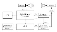
The UDM is a demo that shows capability and performance
of the MC9RS08KA2 and the ultrasonic sensor to build a
distance measurer. Figure 2 shows the basic building block of
this project.


The firmware generates a 40 kHz burst signal. After the 10 cycle
burst is completed, a variable that measures the distance is
activated. This variable measures the time sound takes to rebound
and is used for distance calculation.

The burst signal goes to the ultrasonic transmitter (US Tx) and is
transmitted as ultrasound through the air Figure 2. When the wave
is reflected off an object, this wave is captured by the ultrasonic
receiver (US Rx.) This received signal is amplified because it
attenuates as it travels. Afterwards, the signal goes back to the
microcontroller unit (MCU), filters it and calculates the distance.
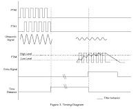
A 40 kHz interrupt is generated by the timer in the MCU. To
perform this, the keyboard interrupt (KBI) is enabled and detects
the external signal. Every time the MCU is interrupted the counter
is increased by three. And the variable used as a counter is
decreased by one for the entrances to the modulus timer module
(MTIM) interrupt service routine (ISR). When this variable is bigger
than eight the ECHO signal is activated. The distance variable is then
set to 0. Refer to Figure 3 for timing diagram. For detailed information
about the firmware see Figure 3.


read more "Ultrasonic Distance Sensor with the Microcontroller Project"

Saturday, April 3, 2010

Robot Line Tracking Sensors Circuit

The infrared emitter and detector Sensors
Figure 4. Circuit diagram for the infrared emitter/detector line
sensor for the MIT Handy Board. If you plan on making the
sensor from color LEDs and Cds photocells, replace the IR
emitter with a red LED and the IR detector with a Cds photocell.
Click here for a circuit diagram if the sensor is used with other
microcontrollers. Note the subtle difference in the way the IR
detector is configured for this design.


more

Building the sensor
Here is the electronic circuit of the LDR based line sensor we
used in our robots in the Robocon 2007 competition. As you
can see it is composed of eight cells, each one resembling the
cell in figure 3.B. There are many reasons to choose to build
a sensor with exactly eight cells, no more, no less: Eight can
provide enough precision, it connects directly to one port of
the microcontroller, and is represented by one single Byte of
data, making it easier to implement in the programming and
in the memory of an 8 bit microcontroller.


more

Photo Interrupters
The LED emits infrared radiation. If the Photo Interrupter passes
over a white surface, the infrared light is reflected back and is
detected by the phototransistor. Let us assume that this is the
case for the right (shown in red) photo interrupter assembly. The
result is that the emitter-collector resistance drops and a large
current flows through the red 27k resistor. This created a large
voltage drop across this resistor and VR is reduced to near zero.
If at the same time, the left photo interrupter assembly (shown
in blue) is over the black line, the radiation is not reflected back
to the phototransistor and the emitter-collector resistance
remains high. This results in a small current through the blue 27k
resistor. The resulting small voltage drop across this resistor
leads to a high value of ~9 V for VL. We send these two voltages
to a comparator, which then makes one of the two wheels of the
robot rotate in such a fashion that it turns to the left.


read more "Robot Line Tracking Sensors Circuit"

Friday, April 2, 2010

Digital Light Sensor to MICROCONTROLLER Circuit


ISL29001


The ISL29001 is an integrated ambient light sensor with
ADC and I2C interface. With a spectral sensitivity curve
matched to that of the human eye, the ISL29001 provides
15-bit effective resolution while rejecting 50Hz and 60Hz
flicker caused by artificial light sources.
In normal operation, the ISL29001 consumes less than
300µA of supply current. A software power-down mode
controlled via the I2C interface disables all but the I2C
interface. A power-down pin is also provided, which reduces
power consumption to less than 1µA.
The ISL29001 includes an internal oscillator, which provides
100ms automatic integration periods, or can be externally
timed by I2C commands. Both the internal timing and the
illuminance resolution can be adjusted with an external
resistor.

ISL29001 datasheet pdf


Microcontroller Advanced Kit - Light Sensor Project

This tutorial shows how to set up a microcontroller based
system that converts a signal from a light sensor to a 6 bit
digital value. This value can be used by the microcontroller,
perhaps for a robotic controller, or as in this tutorial, sent to
the PC. It uses the AT89C2051 microcontroller to collect
data and send it to the PC. A MAX232CPE chip is used to
convert the signals from and to RS232 levels for sending
and receiving through the serial port. The 2051 microcontroller
has a built in analog comparator that is used to make a
simple analog to digital converter to convert the light sensor
output to a digital value.


read more "Digital Light Sensor to MICROCONTROLLER Circuit"

Thursday, April 1, 2010

Light Sensor Circuit 2


Light-controlled pond pump
This circuit was constructed to control the pump in a garden
pond, so that it automatically turns on at dawn and off again
at dusk. Not only does this mean that we don’t have to get
cold and wet when turning the pump on or off manually but
it’s also one less job for our kind neighbours when we go
away on holidays!


more

Light Detection Using A Phototransistor and Voltage
Comparator
This page describes an example project that turns on a red
LED when light is dim and a green LED when light is bright.
Or more to the point, changes color when objects (such as
a fan blade) pass in front of it.Because the lighting required

to enable either LED is controlled by individual potentiometers,

they can be set such that either, neither, or both LEDs turn on.

That is, the red LED doesn't have to turn on simply because the

green LED turned off.


more

Internals of RCX Input Ports and Sensors
When it comes to the active Sensors these are much more
complicated inside as can be seen from the figures 4 to 7.
There is however still a simple relationship between the raw
value measured and the sensor resistance if the A/D
conversion takes place with no power is supplied to the


more


Laser Pointer Triggered On/Off Switch
Remote control is commonly performed with either modulated
infrared emitters or radio-frequency wireless transmitters.
During a boring presentation, it occurred to me that the
presenter could control a slide show by aiming their laser
pointer at a list of commands with bullet-point targets.
Alternatively, someone lying in bed could set the clock
alarm/snooze (across the room) or turn off lights by simply
aiming the laser dot at the correct spot on the desired object.


read more "Light Sensor Circuit 2"

Monday, March 29, 2010

Light Sensor Circuit 1

Tiny Light Sensor With Logic Output Draws Less
Than 10µA

A light-sensing circuit that consumes very little power can
serve as an automatic backlight sensor in portable instruments.
This function is easily implemented with a logic gate or
Schmitt-trigger inverter, but those approaches draw a
considerable amount of supply current.


Figure 1. This light sensor provides a low-to-high output
transition at a light level determined by the value of R1.
more


Sensing Light with a Programmable Gain Amplifier
INTRODUCTION
Photo Sensors bridge the gap between light and electronics.
Microchip’s Programmable Gain Amplifiers
(PGAs) are not well suited for precision applications
(such as CT scanners), but they can be effectively used
in position photo sensing applications minus the headaches
of amplifier stability.


Photo Sensors can be connected directly to Microchip’s PGA.
Based on the level ofluminance to the photo sensor, the gain
of the signal can be changed through the SPI™ port of the
MCP6S26, six-channel PGA.
more pdf

8 Photo-Detector Circuitboards
Visible and Infrared Light
A new version of the 8 Photo-Detector circuitboard where the
Outputs Are LOW When The Inputs Are LOW.
(The LEDs are ON when the Phototransistors are exposed to light.)


more


MAKING A LIGHT / DARK SENSOR
Opposite is a simple light/ dark sensor. This can be connected
as an input or switch to another circuit. The Sensors has three
green wires (1, 2 and 3). Wire 2 should always be connected
to one of the inputs. If wire 1 is also connected then the sensor
acts as a dark sensor. If wires 2 and 3 are connected to the
inputs then sensor operates as a light sensor.


read more "Light Sensor Circuit 1"

Sunday, March 28, 2010

Ultrasonic Sensor Circuit 3

Arduino + Ultrasonic sensor + MP3

In this project for
Martí Guixé we built a small autonomous device
with
Arduino that can detect the presence of people with an
ultrasonic sensor. It then proceeds to play an MP3 song with a
Yampp Industrial II


Ultrasonic range finder uses few components


Measuring distance with ultrasonic signals requires a transmitting
ultrasonic transducer; a medium, such as air or water; a reflecting
surface or object; a receiving ultrasonic transducer; and a
time-of-flight measurement circuit. The speed of sound in air at
20 C is approximately 343m/sec, which translates to about 1 in. Per
74 Wsec. Doubling the time gives you the round-trip speed, which
is 1 in. per 148 Wsec. Four aspects of the system limit the
maximum measurable distance: the amplitude of the sound wave,
the texture of the reflecting surface, the angle of the surface with
respect to the incident sound wave, and the sensitivity of the
receiving transducer. The receiving transducer's direct reception
of the sonar pulse—and not the echo—usually dictates the
minimum measurable distance.


Circuit drawingfor Ultrasonic Range Meter


read more "Ultrasonic Sensor Circuit 3"

Saturday, March 13, 2010

Ultrasonic Sensor Circuit 2

Ultra-Sonic Ranging Design
This project started after I looked at the Polaroid Ultrasonic
Ranging module. It has a number of disadvantages for use in
small robots etc.
-The maximum range of 10.7 metre is far more than is normally
required, and as a result
-The current consumption, at 2.5 Amps during the sonic burst is truly horrendous.
-The 150mA quiescent current is also far too high.
-The minimum range of 26cm is useless. 1-2cm is more like it.
- The module is quite large to fit into small systems, and
- It’s EXPENSIVE.
Here in the UK from Maplin Electronics, the module costs GB38.00
and the transducer costs a further GB17.00. In fairness, the Polaroid
module does the job it was intended to do, which requires the range,
but that job is not to provide the eyes of a small robot.


more


Ultrasonic switch
Description.
A different type of remote control circuit employing ultrasonic signals
is given here.
The transmitter part of the circuit is build around IC1(NE 555).
The IC1 is wired as an astable multi vibrator operating at 40KHz.
The output of IC1 is amplifier the complementary pair of transistors
( Q1 & Q2) and transmitted by the ultrasonic transmitter K1.
The push button switch S1 is used the activate the transmitter.
The receiver uses an ultrasonic sensor transducer (K2) to
sense the ultrasonic signals. When an ultrasonic signal is falling on
the sensor, it produces a proportional voltage signal at its output.
This weak signal is amplified by the two stage amplifier circuit
comprising of transistors Q3 and Q4.The output of the amplifier
is rectified by the diodes D3 & D4.The rectified signal is given to
the inverting input of the opamp which is wired as a comparator.
When ever there is an ultrasonic signal falling on the receiver,
the output of the comparator activates the transistors Q5 & Q6
to drive the relay. In this way the load connected via the relay
can be switched. The diode D5 is used as a free wheeling diode.


more


Ultrasonic Sonar Range Finder with I2C Interface for Mobile Robots

The hardware described here is built up on a single sided PCB, size
49 mm x 50 mm. An Atmel AVR ATtiny26 microcontroller handles all the
needed tasks: I2C slave operation: communication to the I2C master
Stimulation of a resonant circuit embedding the ultrasonic sender Murata
MA40B8S by 40 kHz PWM signal with defined duty cycle ratio
Adjusting the amplification (from 200 to 3500 in 16 steps) during echo
measurement according to a fixed time schedule (change of effective
resistors in the OpAmp feedback circuit) Time measurement until the
ultrasonic echo is received by the Murata MA40B8R

read more "Ultrasonic Sensor Circuit 2"

Thursday, March 11, 2010

Ultrasonic Sensor Circuit 1

Ultrasonic Position System
The ultrasonic position system uses ultrasonic transmitters/receivers
to triangulate position of the robots used in GE423. Each of three
transmitters uses a distinct frequencies: 23 kHz, 31 kHz, and 40 kHz.
The 2812 DSP is used to measure signal timing and calculate
position based on these values. The design of the electronics, as
well as discussion of the software development is presented below.
1.2 Transmit Circuit
A schematic of the transmit circuit looks like


more

Ultrasonic Transmiter


The photo depicts the schematics for an Ultrasonic Transmitter
which will send a signal out into it's surrounding area.
The Ultrasonic receiver will detect this signal once it bounces
off from an object. The combination of these two Sensors will
allow the aerial robot to detect objects in its path and maneuver
around the objects. These Sensors will be attached in front of
the plane. These Sensors will also help the robot navigate
through the halls of any building.. This tutorial will show how to
construct and test one pair of ultrasonic proximity receiver and
transmitter.
more

Ultrasonic Receiver


The photo depicts the schematics for an Ultrasonic Receiver which
will detect the signal from the Ultrasonic Transmitter once it
bounces off from an object. The combination of these two Sensors
will allow the aerial robot to detect objects in its path and maneuver
around the objects. These Sensors will be attached in front of the
plane. These Sensors will also help the robot navigate through the
halls of any building.. This tutorial will show how to construct and
test one pair of ultrasonic proximity receiver and transmitter.
more

Sonar Sensors


This is a simple system. The transmitter emits an ultrasonic signal
(40kHz). The 555 timer chip of the transmitter provides the driving
40kHz signal. Every time the reset pin (pin4) of the 555 timer goes
high, a resulting signal of 40kHz on pin 3 is used to drive the
ultrasonic transducer. Then, the receiver simply listens for the return
echo after it bounces off an object. The small echo signal, when
detected, is amplified 1000 times using a standard operational
amplifier (LM741 op-amp). The signal is then fed into a tone
decoder (LM567) set to lock onto a 40kHz signal. The output of the
tone decoder is HIGH when no echo is heard and swings LOW
when an echo is detected. The output from the tone decoder can
now be fed into a microcontroller or some other type of IC to
determine when an echo was received. To help minimize false
triggering, the output is fed into a voltage comparator set to trigger
at the appropriate level. The LED at the output of the comparator
acts as a visual indicator when an echo is detected (very useful
when debugging). The typical range of this system is from a few
inches to 5-6 feet, depending on the quality of the components,
shielding, and most important, tuning.

more
read more "Ultrasonic Sensor Circuit 1"