Showing posts with label Ultrasonic. Show all posts

Friday, April 16, 2010

Ultrasonic Distance Sensor with the Microcontroller Project


Accurate Ultrasonic Distance Measurement Project

Abstract - This paper introduces a different approach to
the measurement of the time-of-flight of ultrasonic signals.
Frequency variation monitoring and recording is used to
determine accurately the arrival time of the ultrasonic signal.
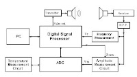
A high speed Digital Signal Processor (D.S.P.) is used for
both: transmission and direct measurement of the frequency
of the incoming signal in every single period and with an
accuracy of about 0.1%. The proposed configuration offers
small size and low cost solution to displacement
measurements with a remarkable performance in terms of
accuracy, range and measurement time.

THE SYSTEM
The configuration of the proposed system is based on the
capabilities of accurate time measurement of modern microcontrollers.
The usual series of microcontrollers can not be
used in this application mainly because of their relatively
low frequency of operation (clock frequency) which affects
the accuracy of time measurement within one single period.
They can not offer the required fast and accurate frequency
measurement. A high performance system may therefore be
built only on a more powerful microcontroller. Larger
systems (personal computer type, etc) are avoided for
practical reasons; the overall measurement system should be
cost-effective and small sized.

More pdf


Ultrasonic Distance Sensor Implemented
with the Microcontroller Project

Linear measurement is a problem that a lot of
applications in the industrial and consumer market
segment have to contend with. Ultrasonic technology is
one of the solutions used by the industry. However, an
optimized balance between cost and features are a must
for almost all target applications. The ultrasonic distance
measurer (UDM) is used mainly when a non-contact
measurer is required. This is the type of solution this
document explains using a simple robot toy
implementation.

Description
The UDM is a demo that shows capability and performance
of the MC9RS08KA2 and the ultrasonic sensor to build a
distance measurer. Figure 2 shows the basic building block of
this project.


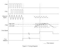
The firmware generates a 40 kHz burst signal. After the 10 cycle
burst is completed, a variable that measures the distance is
activated. This variable measures the time sound takes to rebound
and is used for distance calculation.

The burst signal goes to the ultrasonic transmitter (US Tx) and is
transmitted as ultrasound through the air Figure 2. When the wave
is reflected off an object, this wave is captured by the ultrasonic
receiver (US Rx.) This received signal is amplified because it
attenuates as it travels. Afterwards, the signal goes back to the
microcontroller unit (MCU), filters it and calculates the distance.
A 40 kHz interrupt is generated by the timer in the MCU. To
perform this, the keyboard interrupt (KBI) is enabled and detects
the external signal. Every time the MCU is interrupted the counter
is increased by three. And the variable used as a counter is
decreased by one for the entrances to the modulus timer module
(MTIM) interrupt service routine (ISR). When this variable is bigger
than eight the ECHO signal is activated. The distance variable is then
set to 0. Refer to Figure 3 for timing diagram. For detailed information
about the firmware see Figure 3.

read more "Ultrasonic Distance Sensor with the Microcontroller Project"

Sunday, March 28, 2010

Ultrasonic Sensor Circuit4

40kHz Ultrasonic Driver Circuit for a few pounds

Here is a circuit diagram for an ultrasonic driver circuit suitable
for the the Speed of ultrasound and Lloyd's Mirror using
Ultrasonic Waves experiments. Test the circuit on a plug-in
prototype board to make sure I've transcribed the component
values correctly. I got the circuit to work on a plug-in prototype
board before it was transferred to a printed circuit board (PCB).
The circuit should work with strip board so you shouldn't need
to make a PCB. If somebody does do PCB artwork (or a strip
board layout) they should publish it on the www and I'll link to it.
Many basic electronics books explain the operation of the 555
chip (the 556 chip is a package of two 555 circuits in a single chip).


Ultrasonic Reflectance Detector
This circuit detects motion within approximately 5 inches of
a piezo-ceramic element ultrasonic transducer. The detection
distance is much smaller than obtainable with other ultrasonic
techniques, however, it only requires a single transducer, as
opposed to the two-transducer arrangement typically found in
other designs. The short-range detection is adequate for many
applications, such as proximity-operated commodity dispensers
or tamper alarms for merchandise cases.


Ultrasonic Range Sensor
1 is the connection to the RCX. D1 - D4 form a bridge rectifier
to obtain local power from the RCX which is stored on C7 and
regulated to 5V by U1, a low power, low dropout regulator.
The microcontroller, U3 is programmed to generate a burst of
8 x 40KHz pulses on pin 6. Q1 switches current into L1 creating
a "flyback" voltage output to Y2, the ultrasonic transmitter, of
about 20V peak. The 40KHz is based on a software division of
the 10MHz reference (the ceramic resonator, Y1, in this case).
Y3, the ultrasonic receiver, is band-limited by L2, to stop normal
sound and vehicle vibration from being the dominant input. L2
is chosen to form a resonant circuit with the self capacitance of
the receiver piezo. It should be peaked for 40KHz. U2D and
U2A are the primary gain stages to get the millivolt level signals
up to a couple of volts.


read more "Ultrasonic Sensor Circuit4"

Ultrasonic Sensor Circuit 3

Arduino + Ultrasonic sensor + MP3

In this project for
Martí Guixé we built a small autonomous device
with
Arduino that can detect the presence of people with an
ultrasonic sensor. It then proceeds to play an MP3 song with a
Yampp Industrial II


Ultrasonic range finder uses few components


Measuring distance with ultrasonic signals requires a transmitting
ultrasonic transducer; a medium, such as air or water; a reflecting
surface or object; a receiving ultrasonic transducer; and a
time-of-flight measurement circuit. The speed of sound in air at
20 C is approximately 343m/sec, which translates to about 1 in. Per
74 Wsec. Doubling the time gives you the round-trip speed, which
is 1 in. per 148 Wsec. Four aspects of the system limit the
maximum measurable distance: the amplitude of the sound wave,
the texture of the reflecting surface, the angle of the surface with
respect to the incident sound wave, and the sensitivity of the
receiving transducer. The receiving transducer's direct reception
of the sonar pulse—and not the echo—usually dictates the
minimum measurable distance.


Circuit drawingfor Ultrasonic Range Meter


read more "Ultrasonic Sensor Circuit 3"

Saturday, March 13, 2010

Ultrasonic Sensor Circuit 2

Ultra-Sonic Ranging Design
This project started after I looked at the Polaroid Ultrasonic
Ranging module. It has a number of disadvantages for use in
small robots etc.
-The maximum range of 10.7 metre is far more than is normally
required, and as a result
-The current consumption, at 2.5 Amps during the sonic burst is truly horrendous.
-The 150mA quiescent current is also far too high.
-The minimum range of 26cm is useless. 1-2cm is more like it.
- The module is quite large to fit into small systems, and
- It’s EXPENSIVE.
Here in the UK from Maplin Electronics, the module costs GB38.00
and the transducer costs a further GB17.00. In fairness, the Polaroid
module does the job it was intended to do, which requires the range,
but that job is not to provide the eyes of a small robot.


more


Ultrasonic switch
Description.
A different type of remote control circuit employing ultrasonic signals
is given here.
The transmitter part of the circuit is build around IC1(NE 555).
The IC1 is wired as an astable multi vibrator operating at 40KHz.
The output of IC1 is amplifier the complementary pair of transistors
( Q1 & Q2) and transmitted by the ultrasonic transmitter K1.
The push button switch S1 is used the activate the transmitter.
The receiver uses an ultrasonic sensor transducer (K2) to
sense the ultrasonic signals. When an ultrasonic signal is falling on
the sensor, it produces a proportional voltage signal at its output.
This weak signal is amplified by the two stage amplifier circuit
comprising of transistors Q3 and Q4.The output of the amplifier
is rectified by the diodes D3 & D4.The rectified signal is given to
the inverting input of the opamp which is wired as a comparator.
When ever there is an ultrasonic signal falling on the receiver,
the output of the comparator activates the transistors Q5 & Q6
to drive the relay. In this way the load connected via the relay
can be switched. The diode D5 is used as a free wheeling diode.


more


Ultrasonic Sonar Range Finder with I2C Interface for Mobile Robots

The hardware described here is built up on a single sided PCB, size
49 mm x 50 mm. An Atmel AVR ATtiny26 microcontroller handles all the
needed tasks: I2C slave operation: communication to the I2C master
Stimulation of a resonant circuit embedding the ultrasonic sender Murata
MA40B8S by 40 kHz PWM signal with defined duty cycle ratio
Adjusting the amplification (from 200 to 3500 in 16 steps) during echo
measurement according to a fixed time schedule (change of effective
resistors in the OpAmp feedback circuit) Time measurement until the
ultrasonic echo is received by the Murata MA40B8R

read more "Ultrasonic Sensor Circuit 2"

Thursday, March 11, 2010

Ultrasonic Sensor Circuit 1

Ultrasonic Position System
The ultrasonic position system uses ultrasonic transmitters/receivers
to triangulate position of the robots used in GE423. Each of three
transmitters uses a distinct frequencies: 23 kHz, 31 kHz, and 40 kHz.
The 2812 DSP is used to measure signal timing and calculate
position based on these values. The design of the electronics, as
well as discussion of the software development is presented below.
1.2 Transmit Circuit
A schematic of the transmit circuit looks like


more

Ultrasonic Transmiter


The photo depicts the schematics for an Ultrasonic Transmitter
which will send a signal out into it's surrounding area.
The Ultrasonic receiver will detect this signal once it bounces
off from an object. The combination of these two Sensors will
allow the aerial robot to detect objects in its path and maneuver
around the objects. These Sensors will be attached in front of
the plane. These Sensors will also help the robot navigate
through the halls of any building.. This tutorial will show how to
construct and test one pair of ultrasonic proximity receiver and
transmitter.
more

Ultrasonic Receiver


The photo depicts the schematics for an Ultrasonic Receiver which
will detect the signal from the Ultrasonic Transmitter once it
bounces off from an object. The combination of these two Sensors
will allow the aerial robot to detect objects in its path and maneuver
around the objects. These Sensors will be attached in front of the
plane. These Sensors will also help the robot navigate through the
halls of any building.. This tutorial will show how to construct and
test one pair of ultrasonic proximity receiver and transmitter.
more

Sonar Sensors


This is a simple system. The transmitter emits an ultrasonic signal
(40kHz). The 555 timer chip of the transmitter provides the driving
40kHz signal. Every time the reset pin (pin4) of the 555 timer goes
high, a resulting signal of 40kHz on pin 3 is used to drive the
ultrasonic transducer. Then, the receiver simply listens for the return
echo after it bounces off an object. The small echo signal, when
detected, is amplified 1000 times using a standard operational
amplifier (LM741 op-amp). The signal is then fed into a tone
decoder (LM567) set to lock onto a 40kHz signal. The output of the
tone decoder is HIGH when no echo is heard and swings LOW
when an echo is detected. The output from the tone decoder can
now be fed into a microcontroller or some other type of IC to
determine when an echo was received. To help minimize false
triggering, the output is fed into a voltage comparator set to trigger
at the appropriate level. The LED at the output of the comparator
acts as a visual indicator when an echo is detected (very useful
when debugging). The typical range of this system is from a few
inches to 5-6 feet, depending on the quality of the components,
shielding, and most important, tuning.

more
read more "Ultrasonic Sensor Circuit 1"