The HD44780 dot-matrix liquid crystal display controller and driver LSI displays alphanumeric characters and symbols. It can be configured to drive a dot-matrix liquid crystal display when interfaced with a processor. A single HD44780 can display up to one 8-character line or two 8-character lines. The HD44780 supports 8 dot character fonts and 32 5 ´ 10 dot character fonts for a total of 240 different character fonts.
2.1 Function Description of LCD
The following section will introduce the user with some of the important features of the liquid crystal display, that are important for interfacing with the liquid crystal display through software.
2.1.1 Registers of LCD
The HD44780 has two 8-bit registers, an instruction register (IR) and a data register (DR). The IR stores instruction information, such as display clear and cursor shift, and address information for display data RAM (DDRAM) and character generator RAM (CGRAM). The DR temporarily stores data to be written into DDRAM or CGRAM and temporarily stores data to be read from DDRAM or CGRAM. Data written into the DR is automatically written into DDRAM or CGRAM by an internal operation. The DR is also used for data storage when reading data from DDRAM or CGRAM. When address information is written into the IR, data is read and then stored into the DR from DDRAM or CGRAM by an internal operation.
2.1.2 Busy Flag of LCD
When the busy flag is 1, the HD44780U is in the internal operation mode, and the next instruction will not be accepted. When RS = 0 and R/W = 1 (Table 1), the busy flag is output to DB7. The next instruction must be written after ensuring that the busy flag is 0. The following diagram can visualize the timing diagram for the busy flag check for the LCD.
 Checking the Busy Flag (BF) of LCD
2.1.3 Address Counter of LCD
The address counter (AC) assigns addresses to both DDRAM and CGRAM. When an address of an instruction is written into the IR, the address information is sent from the IR to the AC. Selection of either DDRAM or CGRAM is also determined concurrently by the instruction. After writing into (reading from) DDRAM or CGRAM, the AC is automatically incremented by 1 (decremented by 1). The AC contents are then output to DB0 to DB6 when RS = 0 and R/W = 1.
2.2 Initializing by Internal Reset Circuit of LCD
An internal reset circuit automatically initializes the HD44780 when the power is turned on. The following instructions are executed during the initialization. The busy flag (BF) is kept in the busy state until the initialization ends (BF = 1). The busy state lasts for 10 ms after VCC rises to 4.5 V.
1. Display clear
2. Function set:
DL = 1; 8-bit interface data
N = 0; 1-line display
F = 0; 5 ´ 8 dot character font
3. Display on/off control:
D = 0; Display off
C = 0; Cursor off
B = 0; Blinking off
4. Entry mode set:
I/D = 1; Increment by 1
S = 0; No shift
2.3 Pin Configuration
The pin configuration of LCD along with their functionality is shown below
Table 1: Pin Assignments of HD44780

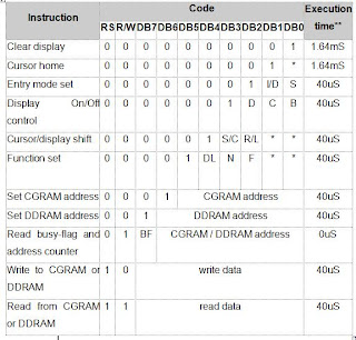
2.4 Instruction Set of LCD
Here is the instruction set summary of HD44780 LCD, also some explanation is provided in the following table.
Table 2: Instruction Set Summary of HD44780
2.1 Function Description of LCD
The following section will introduce the user with some of the important features of the liquid crystal display, that are important for interfacing with the liquid crystal display through software.
2.1.1 Registers of LCD
The HD44780 has two 8-bit registers, an instruction register (IR) and a data register (DR). The IR stores instruction information, such as display clear and cursor shift, and address information for display data RAM (DDRAM) and character generator RAM (CGRAM). The DR temporarily stores data to be written into DDRAM or CGRAM and temporarily stores data to be read from DDRAM or CGRAM. Data written into the DR is automatically written into DDRAM or CGRAM by an internal operation. The DR is also used for data storage when reading data from DDRAM or CGRAM. When address information is written into the IR, data is read and then stored into the DR from DDRAM or CGRAM by an internal operation.
2.1.2 Busy Flag of LCD
When the busy flag is 1, the HD44780U is in the internal operation mode, and the next instruction will not be accepted. When RS = 0 and R/W = 1 (Table 1), the busy flag is output to DB7. The next instruction must be written after ensuring that the busy flag is 0. The following diagram can visualize the timing diagram for the busy flag check for the LCD.
2.1.3 Address Counter of LCD
The address counter (AC) assigns addresses to both DDRAM and CGRAM. When an address of an instruction is written into the IR, the address information is sent from the IR to the AC. Selection of either DDRAM or CGRAM is also determined concurrently by the instruction. After writing into (reading from) DDRAM or CGRAM, the AC is automatically incremented by 1 (decremented by 1). The AC contents are then output to DB0 to DB6 when RS = 0 and R/W = 1.
2.2 Initializing by Internal Reset Circuit of LCD
An internal reset circuit automatically initializes the HD44780 when the power is turned on. The following instructions are executed during the initialization. The busy flag (BF) is kept in the busy state until the initialization ends (BF = 1). The busy state lasts for 10 ms after VCC rises to 4.5 V.
1. Display clear
2. Function set:
DL = 1; 8-bit interface data
N = 0; 1-line display
F = 0; 5 ´ 8 dot character font
3. Display on/off control:
D = 0; Display off
C = 0; Cursor off
B = 0; Blinking off
4. Entry mode set:
I/D = 1; Increment by 1
S = 0; No shift
2.3 Pin Configuration
The pin configuration of LCD along with their functionality is shown below
Table 1: Pin Assignments of HD44780

2.4 Instruction Set of LCD
Here is the instruction set summary of HD44780 LCD, also some explanation is provided in the following table.
Table 2: Instruction Set Summary of HD44780


 Posts
Posts


