Wednesday, January 30, 2013

Control Uninterruptible Power Supply Using PIC17C43 Microcontroller

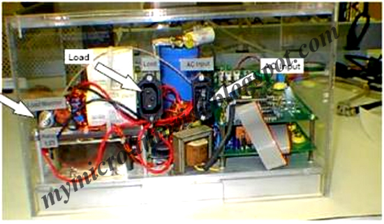
That is a design circuit for Microchip Uninterruptible Power Supply (UPS) reference design with PIC17C43 microcontroller. Here’s the figure of the power supply;


At times, power from a wall socket is neither clean nor uninterruptible. Many abnormalities such as blackouts, brownouts, spikes, surges, and noise can occur. Under the best conditions, power interruptions can be an inconvenience. At their worst, they can cause loss of data in computer systems or damage to electronic equipment.

It is the function of an Uninterruptible Power Supply (UPS) to act as a buffer and provide clean, reliable power to vulnerable electronic equipment. The basic concept of a UPS is to store energy during normal operation (through battery charging) and release energy (through DC to AC conversion) during a power failure. UPS systems are traditionally designed using analog components. Today these systems can integrate a microcontroller with AC sine wave generation, offering the many benefits. The PIC17C43 microcontroller handles all the control of the UPS system. The PIC17C43 is unique because it provides a high performance and low cost solution not found in other microcontrollers.
read more "Control Uninterruptible Power Supply Using PIC17C43 Microcontroller"

Control Centigrade and Fahrenheit Scale Digital Thermometer Using LCD Display

This is a design circuit for Digital thermometers are cool devices as they show temperatures in human readable formats. This digital thermometer project is based on a PIC16F688 microcontroller and a DS1820 temperature sensor, and it displays temperature on a character LCD screen in both Celsius and Fahrenheit scales. I selected PIC16F688 for this project because it is cheap (I bought one for $1.50). DS1820 is a 3-pin digital temperature sensor from Dallas semiconductors (now Maxim) which is designed to measure temperatures ranging from -55 to +125 °C in 0.5 °C increments. Here’s the figure of the circuit;


The firmware I have written is able to read and display the entire temperature range of DS1820. In order to test for temperature measurements below 0°C, I put the sensor inside my freezer. While trying this, don’t put the whole unit inside the freezer as LCD display unit may stop working at the freezer temperature. Similarly, bringing a soldering iron tip close to the sensor can do testing for the higher range temperature values.
read more "Control Centigrade and Fahrenheit Scale Digital Thermometer Using LCD Display"

Friday, January 25, 2013

Control Using Reset IC in Microcontroller

This is a the design of microcontroller based electronics project, the use of Reset IC is critical for highly critical applications that need to ensure that the MCU will only operate at its optimum voltage. Without the use of reset circuitry, the MCU may go into a tristate of which it may go into abnormal operation. This is the figure if the circuit;


During power up, once Vcc exceeds the reset threshold, the reset line will be kept low for a period after which the line will be pulled high. This resets the MCU afterwhich it will go into normal operation.
 
If the Vcc drops below the reset threshold, the reset pin will go low. It will stay low for at least the reset time out period and go back to high again. This operation will ensure that the MCU power supply is monitored and will only go into operation when the Vcc is within the range of its operation. The threshold voltage of the IC is chosen based on the minimum Vcc of the MCU. MCU supply can range from 1.8V to 5.0V and a suitable IC can be chosen to monitor the supply voltage to the MCU.
read more "Control Using Reset IC in Microcontroller"

Control The Voltage Regulator

The DC voltage produce by this circuit is depend on the load; the heavier the load (more current to the load) means the capacitor discharge time will be more faster and as a result the DC voltage output level will be drop. The circuit above is called unregulated AC to DC converter; because it could not maintain its voltage output level, this kind of power source could not be use in electronic circuit that required constant voltage level in order to operate properly such as in digital and microcontroller circuit. Therefore we need what is called Voltage Regulator Circuit and at the same time works as the DC to DC voltage step down.
 

The first one is the analog voltage regulator, this type of regulator operate the transistor in its linear region (current gainer). The current supplied to the transistor base lead is depend on the voltage different between the reference voltage and output voltage apply to the error amplifier input; for example when the output voltage is greater than the reference voltage, than the error amplifier will make the transistor to conduct less, this mean the voltage drop across the collector and emitter (Vce) will be increase this will make the output voltage to decrease and vice verse. With output voltage being continuously compared to the reference voltage (close loop feedback) by the error amplifier, this kind of circuit could maintain its voltage output level constantly. The disadvantage of using this type of voltage regulator is the power dissipation (power lost as a heat) on the transistor is high especially when we want to use 5 Volt output from 11.33 volt from the unregulated DC source or drain lot of current from it.

The second one is the most efficient voltage regulator as this type of voltage regulator operates the transistor in its saturate region or known as a switching voltage regulator. The working principal is the same as the analog one, but instead of using the constant current to the transistor base lead; this voltage regulator type use pulse current or known as PWM (Pulse Width Modulation) to the transistor base lead and this make the transistor to turn on and off according to the PWM duty cycle supplied by the error amplifier. Therefore by changing the PWM duty cycle we could change the average voltage drop across the collector and emitter (Vce). The inductor (L) is used to release its energy to the load through the diode (D) when the transistor is turn off; and when the transistor is turn on then the transistor will supply the current to the load and the inductor will store the energy in the electromagnetic form; in other word the inductor and diode will ensure that the load will always get a constant current when the transistor is turn off.

read more "Control The Voltage Regulator"

Control Making a Binary Clock Using a PIC Microcontroller

This is a design circuit for binary clock circuit. This circuit is the same hardware as the led matrix project using a 16F88 PIC microcontroller and an LED matrix.  Its worth taking a look there as the same hardware description applies on how to multiplex the display. This is the figure of the circuit;


To display hours, minutes and seconds (2 digits each) you need 6 binary digits in total (depending on whether you use a 24 hour clock the top digit needs only 1 or 2 LEDs).
read more "Control Making a Binary Clock Using a PIC Microcontroller"

Control DC to DC Step-Up Regulator

This is a design circuit for the Maxim MAX756 is the sample of easy to use DC to DC step-up switching regulator; this chip is used to increase the typically low input DC voltage 1.1 volt - 1.8 volt to the output DC voltage of 3.3 Volt or 5 Volt at maximum 200mA load (300mA on 3.3 Volt output). This is the figure of the circuit;


This means you could easily power your microcontroller project using just a single AA/AAA battery. This kind of step-up power is widely use on digital and microcontroller circuit that powered by low input voltage battery such as micro alkaline 1.5 volt battery. The basic schematic for 5 volt output from 1.5 volt battery. The output voltage of Maxim MAX756 could be selected from 5 volt or 3.3 volt by putting logical low or high on pin 2 (3/5), it also supply the low output indicator detector to the circuit if needed through the pin 4 (LBO). The following picture shows the Maxim MAX756 IC circuit powering the microcontroller’s board using just 1 AA alkaline battery (1.5 Volt).
read more "Control DC to DC Step-Up Regulator"

Monday, January 21, 2013

Control PLC omron to VB example

In this post , I'd like to Change the state of PLC (run,monitor,stop) from the VB.I send the command from VB to PLC and then PLC responds and the change their state ,
please make VB interface below:


write the source code below:
Dim data 'General Declaration
Private Sub kirim()
Dat$ = data
l = Len(Dat$)
A = 0
For I = 1 To l
Opo$ = Mid$(Dat$, I, 1)
A = Asc(Opo$) Xor A
Next I
FCS$ = Hex$(A)
If Len(FCS$) = 1 Then

FCS$ = "0" + FCS$
End If
DatTX$ = Dat$ + FCS$ + "*" + Chr$(13)
MSComm1.Output = DatTX$
End Sub

Private Sub cmdKeluar_Click()
End
End Sub

Private Sub cmdMonitor_Click()
data = "@00SC02" '(setting hostlink pada PLC 00)
lblPeringatan.Caption = "MESIN ANDA BERGERAK,BILA ANDA MEMILIH MODE INI,PASTIKAN SAFETY"
lblPeringatan.ForeColor = &HFF&
jawab = MsgBox("ANDA MAU MERUBAH MODE PLC? " & vbCrLf & _
"MONITOR MODE!!!! ", vbYesNo + vbQuestion + vbDefaultButton1, "RUBAH MODE PLC")
If jawab = vbYes Then
cmdProgram.Enabled = True
cmdRun.Enabled = True
cmdMonitor.Enabled = False
kirim
lblModePLC.ForeColor = &H8000000D
lblModePLC.Caption = "PLC SEDANG MODE MONITOR !!!!"
lblPeringatan.Caption = ""
lblPeringatan.ForeColor = &HFFFFFF
End If
lblPeringatan.Caption = ""
lblPeringatan.ForeColor = &HFFFFFF
End Sub

Private Sub cmdProgram_Click()
data = "@00SC00" '(setting hostlink pada PLC 00)
lblPeringatan.Caption = "MESIN ANDA AKAN SHUT DOWN ,BILA ANDA MEMILIH MODE INI"
lblPeringatan.ForeColor = &HFF&
jawab = MsgBox("ANDA MAU MERUBAH MODE PLC? " & vbCrLf & _
"PROGRAM MODE!!!! ", vbYesNo + vbQuestion + vbDefaultButton1, "RUBAH MODE PLC")
If jawab = vbYes Then
cmdProgram.Enabled = False
cmdRun.Enabled = True
cmdMonitor.Enabled = True
kirim
lblModePLC.ForeColor = &HFF&
lblModePLC.Caption = "PLC SEDANG MODE PROGRAM!!!!"
lblPeringatan.Caption = ""
lblPeringatan.ForeColor = &HFFFFFF
End If
lblPeringatan.Caption = ""
lblPeringatan.ForeColor = &HFFFFFF
End Sub


Private Sub cmdRun_Click()
data = "@00SC03" '(setting hostlink pada PLC 00)
lblPeringatan.Caption = "MESIN ANDA BERGERAK,BILA ANDA MEMILIH MODE INI,PASTIKAN SAFETY"
lblPeringatan.ForeColor = &HFF&
jawab = MsgBox("ANDA MAU MERUBAH MODE PLC? " & vbCrLf & _
"PROGRAM MODE!!!! ", vbYesNo + vbQuestion + vbDefaultButton1, "RUBAH MODE PLC")
If jawab = vbYes Then
cmdProgram.Enabled = True
cmdRun.Enabled = False
cmdMonitor.Enabled = True
kirim
lblModePLC.ForeColor = &HFF&
lblModePLC.Caption = "PLC SEDANG MODE RUN!!!!"
lblPeringatan.Caption = ""
lblPeringatan.ForeColor = &HFFFFFF
End If
lblPeringatan.Caption = ""
lblPeringatan.ForeColor = &HFFFFFF
End Sub

Private Sub SET_Click()
data = "@00WR00100001"
kirim
End Sub

Private Sub RESET_Click()
data = "@00WR00100000"
kirim
End Sub

Private Sub Form_Load()
MSComm1.CommPort = 1 '(port PC comm1,tapi tergantung PC anda)
MSComm1.Settings = "9600, e, 7, 2" '(harus sama PC dan PLC)
MSComm1.PortOpen = True
End Sub

read more "Control PLC omron to VB example"

Sunday, January 20, 2013

Control Push button ON VB to Omron PLC

On VB interface you can make SET dan RESET button and Temporary Push Button to commuicate with OMRON PLC, please make VB interface below:


Then Write Source code below
Dim data 'General Declaration
Private Sub kirim()
Dat$ = data
l = Len(Dat$)
A = 0
For I = 1 To l
Opo$ = Mid$(Dat$, I, 1)
A = Asc(Opo$) Xor A
Next I

READ MORE.....

read more "Control Push button ON VB to Omron PLC"

Saturday, January 19, 2013

Control Ladder Diagram Start delta circuit

As we know start delta use for starting induction motor to reduce rush .in this post I made the start delta control with PLC:
Power Wiring diagram for Start Delta:

Star Delta Power Wiring Diagram

READ MORE.....

read more "Control Ladder Diagram Start delta circuit"

Thursday, January 17, 2013

Control Ladder quiz for 3 Groups

I used Mitsubishi PLC, but you can convert the ladder diagram to other PLC type such as siemens, AB, ,omron etc or other as long you configure the I/O.
first make the I/O table :

Input Device:

Device

Address

Note

Push Button 1X1for the first group
Push Button 2X2for the second group
Push button 3X3for the thrid group
Push button 4X4Reset by the judge

Output Device:

READ MORE.....

read more "Control Ladder quiz for 3 Groups"

Control PIC Frequency Counter Operating Up To 50 MHz

This is a design circuit for general theory of operation of this circuit and notes on frequency counting. This circuit is based on PIC microcontrollers for the main control unit of the circuit. This is the figure of the circuit;
 

The LCD is used in 4 bit mode interface so you only need 4 data lines and three control lines and it then fits into a single 8 bit port.

The crystal oscillator is simply a crystal and two capacitors connected to the PIC oscillator port at OSC1 and OSC2. The capacitors can both be fixed at the same value unless you want to tune it using a frequency reference. If you don't have an accurate reference then use fixed capacitors. The PIC micro can be any type that has a Timer 1 hardware and and has enough memory to hold the program. The LED is toggled at the end of every gate time to indicate that the processor is alive - so if there is no input signal you can tell that the software is working.

read more "Control PIC Frequency Counter Operating Up To 50 MHz"

Control Multiple PIC16F84 Proteus Simulated Projects

Proteus is a software tool that allows simulation of various circuits including microcontroller based ones. You can complete entire project with simulator including hardware and software parts. And only then you can move towards manufacturing real device. This page is dedicated only to PIC16F84 microcontroller projects where you can download ready to simulate about 31 complete project. 
 

Projects include implementation of popular interfaces like LCD, Timers, EEPROM writing, Interrupts, I2C and 1-wire communication, motor control and so on. Each project include Proteus project file and microcontroller hex file that has to be attached to model to start simulate.

read more "Control Multiple PIC16F84 Proteus Simulated Projects"

Control MIC 702 Mictronics Circuit

This is a design circuit that can be used to convert a standard LCD interface parallel to serial interface model, use a microcontroller or a dedicated circuit such as the MIC 702 Mictronics you can download the complete data sheet and French by clicking this link. This is a circuit specially designed to transform the parallel interface and LCD display logic integrated asynchronous serial interface standard. This is the figure of the circuit;
 

The MIC 702 is connected directly to the display with which it is perfectly compatible. Notice the connection with only 4 data bits of high weight since the MIC 702 operates in the display mode twice 4 bits. PC side, the connection with the serial output of the PC does not involve any level converter for RS 232 TTL, this role being played by the only resistor R1 22 ohm whose presence is essential. BAUD The tab allows you to choose the operating speed of the circuit between two speeds: 9600 bps up with S1 or S2 with 2400 baud up. The leg POL allows the circuit to interpret the serial data as direct or inverted. As it is in direct RS232 link should be link this foot to ground to indicate the MIC 702 that receives data reversed. Linkage to +5 volts it would receive direct evidence as would be the case if we wanted to use this circuit with a Basic Stamp example.

Subject to use a display not backlit, the total consumption of the circuit is low enough that it can take its power directly from the output control signals to the RS 232. It is the role of diodes D2 and D3 associated with IC1, which is a regulator with low dropout voltage and low consumption. If you insist on using a backlit display, it is possible that consumption of its single backlight exceeds the possibilities of the PC's serial port. You can use an external power supply via the diode D1. A voltage of 9 volts at a flow rate of a hundred mA appropriate.

read more "Control MIC 702 Mictronics Circuit"

Control Driver an RGB LED Using Three Microcontroller Pins

The RGB LED contains three LEDs encased in one shell: Red, Green and Blue (some contain an extra blue led - as blue LEDs generate less output intensity (candela) per mA). It looks like a single white led except that it has four leads - one for the common ground connection and one for each led. This is the figure of the circuit;


This project uses puls width modulation to drive each of the leds in the RGB led. By changing the duty cycle of each PWM signal you can control the average current flowing through each led creating any color you want. The limit is set by the resoelution of the PWM (set at 256 steps per channel). The project relies on persistence of vision to make it appear that the led is continuously driven (the PWM signals must be repeated quickly enough so that you do not see any flicker) at a rate greater than 50Hz (approx). Too slow and you begin to see the led flickering.

By varying the current through each led you can create almost any other color but at close range you only see the individual colors of each LED. To see the 'merged' color view it from a distance or put a diffuser over it. I used a small piece of baking paper - which is transparent enough to let the light through and opaque enough to diffuse the light from the three LEDs. In a proper design you would use a semi-transparent plastic.
read more "Control Driver an RGB LED Using Three Microcontroller Pins"

Saturday, January 12, 2013

Control PLC program 1 button on and off

This is the Ladder diagram program for application one Push button for On and OFF the lamp .Using OMRON PLC type CJ1M.
job description circuit:
1.first time the button is pressed then the lamp ON
2.second time the button is pressed then lights OFF
3.back to a description number 1

Addressing Input and output :

Device

Address

NOTE

Push button 1 (PB1)00.00Chanel 0 bit 0
Lamp01.00Chanel 1 bit 0
Internal Relay 110.00First Sequence(lamp ON)
Internal Relay 210.01second sequence(transisi PB ON ke OFF)
Internal Relay 310.02Thrid Sequence (Lamp OFF)
Internal Relay 410.03Reset back to the first sequence


Wiring I/O of PLC:

READ MORE.....

read more "Control PLC program 1 button on and off"

Control Program PLC 1 tombol on dan off

Pada koleksi program kali ini , saya akan coba membuat aplikasi satu buah tombol untuk On dan OFF sebuah lampu.Dengan menggunakan PLC OMRON type CJ1M.
deskripsi kerja rangkaian:
1.Jika tombol ditekan pertama kali maka lampu ON
2.Jika tombol ditekan yang kedua kali maka lampu OFF
3.Kembali ke deskripsi no1.
Pengalamatan Input dan output:

Device

Alamat/Address

Keterangan

Push button 1 (PB1)00.00Chanel 0 bit 0
Lamp01.00Chanel 1 bit 0
Internal Relay 110.00sequence pertama (lamp ON)
Internal Relay 210.01sequence kedua(transisi PB ON ke OFF)
Internal Relay 310.02sequence ketiga (Lamp OFF)
Internal Relay 410.03Reset kembali ke sequence pertama

Gambar Wiring I/O bisa dilihat di bawah ini:

Buatlah Gambar ladder diagram dibawah ini dan transfer ke PLC:

Demikian koleksi ladder diagram pertama ini , akan dilanjut dengan postingan kedua Program Star Delta
read more "Control Program PLC 1 tombol on dan off"

Friday, January 11, 2013

Control BASIC of MODBUS RTU Serial

What is Modbus?
Modbus is a serial communication protocol developed by Modicon published by Modicon® in 1979 for use with its programmable logic controllers (PLCs). In simple terms, it is a method used for transmitting information over serial lines between electronic devices. The device requesting the information is called the Modbus Master and the devices supplying information are Modbus Slaves. In a standard Modbus network, there is one Master and up to 247 Slaves, each with a unique Slave Address from 1 to 247. The Master can also write information to the Slaves.
The official Modbus specification can be found at www.modbus-ida.org.
What is it used for?
Modbus is an open protocol, meaning that it's free for manufacturers to build into their equipment without having to pay royalties. It has become a standard
communications protocol in industry, and is now the most commonly available means of connecting industrial electronic devices. It is used widely by many manufacturers throughout many industries. Modbus is typically used to transmit signals from instrumentation and control devices back to a main controller or data gathering system, for example a system that measures temperature and humidity and communicates the results to a computer. Modbus is often used to connect a supervisory computer with a remote terminal unit (RTU) in supervisory control and data acquisition (SCADA) systems. Versions of the Modbus protocol exist for serial lines (Modbus RTU and Modbus ASCII) and for Ethernet (Modbus TCP).

READ MORE.....

read more "Control BASIC of MODBUS RTU Serial"

Control Omron PLC and VB via Ethernet

In this post I'd like to share how to connect PLC omron with VB via converter serial to ethernet in this case I use MOXA, please make Vb interface below:

Write the source code below:
Private Sub Command1_Click()
Text1.Text = “”
cmd$ = “@00WR0001FFFF”
Call Checksum(cmd$, cksm$)
command.Text = cmd$ + cksm$ + “*” + Chr$(13)
Winsock1.RemoteHost = “192.168.1.100″
Winsock1.RemotePort = 2101
Winsock1.SendData command.Text
Private Sub Command2_Click()
Text1.Text = “”
cmd$ = “@00WR00010000″
Call Checksum(cmd$, cksm$)
command.Text = cmd$ + cksm$ + “*” + Chr$(13)
Winsock1.RemoteHost = “192.168.1.100″
Winsock1.RemotePort = 2101

READ MORE.....

read more "Control Omron PLC and VB via Ethernet"

Control Power logic or powe meter to Visual basic

This sample application VB for monitoring Diris A20 power meter vendor by SOCOMEC,I use Modbus RTU protocol to communication between Diris A20 and VB.
first make Vb interface below:


write The source code below:
Dim CRCTable(0 To 511) As Byte
Dim CRC_Low, CRC_High As Byte
Private Sub CRC_16(ByVal Data As String, Length As Integer)
Dim i As Integer
Dim Index As Byte
CRC_Low = &HFF
CRC_High = &HFF
For i = 1 To Length

READ MORE.....

read more "Control Power logic or powe meter to Visual basic"

Control Omron PLC talk To VB

in this post I'd like to share about how to make PLC talk to the Visual Basic, and Then make Monitoring the condition of machine or PLC .Visual basic can Read and Write data to the PLC by send message to PLC and PLC send back the responds to the Visual Basic. Connection between PLC and VB used Serial communication Port or Host Link , below the connection diagram between PLC and PC (VB):


We have program PLC below:

e have program PLC below Image description

I want to monitoring the condition of bit 01.00 or 11.00 on VB, and I want to set the setting value timer and monitoring the current value on VB.

  1. Rung no 0 the timer activated by bits 10.00, and the set value store at Register D1
  2. Rung no 1 contact T000 activated coil 11.00 and 01.00
  3. Rung no 2 Move present value of T000 to register D2
  4. rung no3 move register CIO 11 to register D3
  5. Register D0 for set value timer
  6. Register D1 for monitoring timer’s present value
  7. Register D2 for monitoring condition bit 11.00

make the VB interface below:

Image description

Write the Source code below:

Dim data ‘General Declaration
Private Sub kirim()
Dat$ = data
l = Len(Dat$)
A = 0
For I = 1 To l
Opo$ = Mid$(Dat$, I, 1)
A = Asc(Opo$) Xor A
Next I
FCS$ = Hex$(A)
If Len(FCS$) = 1 Then
FCS$ = “0″ + FCS$
End If
DatTX$ = Dat$ + FCS$ + “*” + Chr$(13)
MSComm1.Output = DatTX$
End Sub

Private Sub Command1_Click()
Timer2 = False
Timer3 = True
End Sub

Private Sub Command2_Click()
Timer2 = False
Timer4 = True
End Sub

Private Sub Form_Load()
MSComm1.CommPort = 1 ‘(port PC comm1,tapi tergantung PC anda)
MSComm1.Settings = “9600, e, 7, 2″ ‘(harus sama PC dan PLC)
MSComm1.PortOpen = True
End Sub

Private Sub input_data_Click()
Timer2 = False
dm1 = Len(Text1.Text)
If dm1 = 4 Then
Timer1 = True
Else
jawab = MsgBox(“SALAH MASUKIN DATA BEGO LOH!!(masukkan 4 digit data)” & vbCrLf & _
“MAU INPUT ULANG DATA ?”, vbYesNo + vbQuestion + vbDefaultButton1, “”)
If jawab = vbYes Then
Text1.Text = “”
Text1.SetFocus
Else
End If

End If
End Sub
Private Sub Timer1_Timer()
bil = 1
Do
data = “@00WD0001″ & Text1.Text
kirim
bil = bil + 1
Loop Until bil = 8
Timer2 = True
Timer1 = False
OK = MsgBox(“Data Input Sukses”, vbOKOnly, “”)
End Sub

Private Sub Timer2_Timer()
data = “@00RD00010003″
kirim
Text4.Text = MSComm1.Input
Text5 = Mid(Text4.Text, 19, 1)
Text2 = Mid(Text4.Text, 12, 4)
Text3 = Mid(Text4.Text, 8, 4)
cek1 = Text5.Text
If cek1 = “1″ Then
Shape1.BackColor = &HFF&
Line1.BorderColor = &HFF&
Line2.BorderColor = &HFF&
Line3.BorderColor = &HFF&
Line4.BorderColor = &HFF&
Else
Shape1.BackColor = &H404040
End If
End Sub

Private Sub Timer3_Timer()
bil = 1
Do
data = “@00WR00100001″
kirim
bil = bil + 1
Loop Until bil = 8
Timer2 = True
Timer3 = False
End Sub

Private Sub Timer4_Timer()
bil = 1
Do
data = “@00WR00100000″
kirim
bil = bil + 1
Loop Until bil = 8
Timer2 = True
Timer4 = False
End Sub


read more "Control Omron PLC talk To VB"

Thursday, January 10, 2013

Control MODBUS RTU WITH VB

This is the basic of Serial MODBUS RTU , in this post I would like to share about how to get data from Device Modbus RTU to Visual Basic (PC)First make VB interface below:


Write the source code below:
Dim CRCTable(0 To 511) As Byte
Dim CRC_Low, CRC_High As Byte
Private Sub CRC_16(ByVal Data As String, Length As Integer)
Dim i As Integer
Dim Index As Byte
CRC_Low = &HFF
CRC_High = &HFF
For i = 1 To Length
Index = CRC_High Xor Asc(Mid(Data, i, 1))
CRC_High = CRC_Low Xor CRCTable(Index)
CRC_Low = CRCTable(Index + 256)
Next i
End Sub

Private Sub Command1_Click()
Timer1.Enabled = True
End Sub

Private Sub Command2_Click()
Timer1.Enabled = False
End Sub


Private Sub Form_Load()
MSComm1.PortOpen = True
CRCTable(0) = &H0
CRCTable(1) = &HC1
CRCTable(2) = &H81
CRCTable(3) = &H40
CRCTable(4) = &H1
CRCTable(5) = &HC0
CRCTable(6) = &H80
CRCTable(7) = &H41
CRCTable(8) = &H1
CRCTable(9) = &HC0
CRCTable(10) = &H80
CRCTable(11) = &H41
CRCTable(12) = &H0
CRCTable(13) = &HC1
CRCTable(14) = &H81
CRCTable(15) = &H40
CRCTable(16) = &H1
CRCTable(17) = &HC0
CRCTable(18) = &H80
CRCTable(19) = &H41
CRCTable(20) = &H0
CRCTable(21) = &HC1
CRCTable(22) = &H81
CRCTable(23) = &H40
CRCTable(24) = &H0
CRCTable(25) = &HC1
CRCTable(26) = &H81
CRCTable(27) = &H40
CRCTable(28) = &H1
CRCTable(29) = &HC0
CRCTable(30) = &H80
CRCTable(31) = &H41
CRCTable(32) = &H1
CRCTable(33) = &HC0
CRCTable(34) = &H80
CRCTable(35) = &H41
CRCTable(36) = &H0
CRCTable(37) = &HC1
CRCTable(38) = &H81
CRCTable(39) = &H40
CRCTable(40) = &H0
CRCTable(41) = &HC1
CRCTable(42) = &H81
CRCTable(43) = &H40
CRCTable(44) = &H1
CRCTable(45) = &HC0
CRCTable(46) = &H80
CRCTable(47) = &H41
CRCTable(48) = &H0
CRCTable(49) = &HC1
CRCTable(50) = &H81
CRCTable(51) = &H40
CRCTable(52) = &H1
CRCTable(53) = &HC0
CRCTable(54) = &H80
CRCTable(55) = &H41
CRCTable(56) = &H1
CRCTable(57) = &HC0
CRCTable(58) = &H80
CRCTable(59) = &H41
CRCTable(60) = &H0
CRCTable(61) = &HC1
CRCTable(62) = &H81
CRCTable(63) = &H40
CRCTable(64) = &H1
CRCTable(65) = &HC0
CRCTable(66) = &H80
CRCTable(67) = &H41
CRCTable(68) = &H0
CRCTable(69) = &HC1
CRCTable(70) = &H81
CRCTable(71) = &H40
CRCTable(72) = &H0
CRCTable(73) = &HC1
CRCTable(74) = &H81
CRCTable(75) = &H40
CRCTable(76) = &H1
CRCTable(77) = &HC0
CRCTable(78) = &H80
CRCTable(79) = &H41
CRCTable(80) = &H0
CRCTable(81) = &HC1
CRCTable(82) = &H81
CRCTable(83) = &H40
CRCTable(84) = &H1
CRCTable(85) = &HC0
CRCTable(86) = &H80
CRCTable(87) = &H41
CRCTable(88) = &H1
CRCTable(89) = &HC0
CRCTable(90) = &H80
CRCTable(91) = &H41
CRCTable(92) = &H0
CRCTable(93) = &HC1
CRCTable(94) = &H81
CRCTable(95) = &H40
CRCTable(96) = &H0
CRCTable(97) = &HC1
CRCTable(98) = &H81
CRCTable(99) = &H40
CRCTable(100) = &H1
CRCTable(101) = &HC0
CRCTable(102) = &H80
CRCTable(103) = &H41
CRCTable(104) = &H1
CRCTable(105) = &HC0
CRCTable(106) = &H80
CRCTable(107) = &H41
CRCTable(108) = &H0
CRCTable(109) = &HC1
CRCTable(110) = &H81
CRCTable(111) = &H40
CRCTable(112) = &H1
CRCTable(113) = &HC0
CRCTable(114) = &H80
CRCTable(115) = &H41
CRCTable(116) = &H0
CRCTable(117) = &HC1
CRCTable(118) = &H81
CRCTable(119) = &H40
CRCTable(120) = &H0
CRCTable(121) = &HC1
CRCTable(122) = &H81
CRCTable(123) = &H40
CRCTable(124) = &H1
CRCTable(125) = &HC0
CRCTable(126) = &H80
CRCTable(127) = &H41
CRCTable(128) = &H1
CRCTable(129) = &HC0
CRCTable(130) = &H80
CRCTable(131) = &H41
CRCTable(132) = &H0
CRCTable(133) = &HC1
CRCTable(134) = &H81
CRCTable(135) = &H40
CRCTable(136) = &H0
CRCTable(137) = &HC1
CRCTable(138) = &H81
CRCTable(139) = &H40
CRCTable(140) = &H1
CRCTable(141) = &HC0
CRCTable(142) = &H80
CRCTable(143) = &H41
CRCTable(144) = &H0
CRCTable(145) = &HC1
CRCTable(146) = &H81
CRCTable(147) = &H40
CRCTable(148) = &H1
CRCTable(149) = &HC0
CRCTable(150) = &H80
CRCTable(151) = &H41
CRCTable(152) = &H1
CRCTable(153) = &HC0
CRCTable(154) = &H80
CRCTable(155) = &H41
CRCTable(156) = &H0
CRCTable(157) = &HC1
CRCTable(158) = &H81
CRCTable(159) = &H40
CRCTable(160) = &H0
CRCTable(161) = &HC1
CRCTable(162) = &H81
CRCTable(163) = &H40
CRCTable(164) = &H1
CRCTable(165) = &HC0
CRCTable(166) = &H80
CRCTable(167) = &H41
CRCTable(168) = &H1
CRCTable(169) = &HC0
CRCTable(170) = &H80
CRCTable(171) = &H41
CRCTable(172) = &H0
CRCTable(173) = &HC1
CRCTable(174) = &H81
CRCTable(175) = &H40
CRCTable(176) = &H1
CRCTable(177) = &HC0
CRCTable(178) = &H80
CRCTable(179) = &H41
CRCTable(180) = &H0
CRCTable(181) = &HC1
CRCTable(182) = &H81
CRCTable(183) = &H40
CRCTable(184) = &H0
CRCTable(185) = &HC1
CRCTable(186) = &H81
CRCTable(187) = &H40
CRCTable(188) = &H1
CRCTable(189) = &HC0
CRCTable(190) = &H80
CRCTable(191) = &H41
CRCTable(192) = &H0
CRCTable(193) = &HC1
CRCTable(194) = &H81
CRCTable(195) = &H40
CRCTable(196) = &H1
CRCTable(197) = &HC0
CRCTable(198) = &H80
CRCTable(199) = &H41
CRCTable(200) = &H1
CRCTable(201) = &HC0
CRCTable(202) = &H80
CRCTable(203) = &H41
CRCTable(204) = &H0
CRCTable(205) = &HC1
CRCTable(206) = &H81
CRCTable(207) = &H40
CRCTable(208) = &H1
CRCTable(209) = &HC0
CRCTable(210) = &H80
CRCTable(211) = &H41
CRCTable(212) = &H0
CRCTable(213) = &HC1
CRCTable(214) = &H81
CRCTable(215) = &H40
CRCTable(216) = &H0
CRCTable(217) = &HC1
CRCTable(218) = &H81
CRCTable(219) = &H40
CRCTable(220) = &H1
CRCTable(221) = &HC0
CRCTable(222) = &H80
CRCTable(223) = &H41
CRCTable(224) = &H1
CRCTable(225) = &HC0
CRCTable(226) = &H80
CRCTable(227) = &H41
CRCTable(228) = &H0
CRCTable(229) = &HC1
CRCTable(230) = &H81
CRCTable(231) = &H40
CRCTable(232) = &H0
CRCTable(233) = &HC1
CRCTable(234) = &H81
CRCTable(235) = &H40
CRCTable(236) = &H1
CRCTable(237) = &HC0
CRCTable(238) = &H80
CRCTable(239) = &H41
CRCTable(240) = &H0
CRCTable(241) = &HC1
CRCTable(242) = &H81
CRCTable(243) = &H40
CRCTable(244) = &H1
CRCTable(245) = &HC0
CRCTable(246) = &H80
CRCTable(247) = &H41
CRCTable(248) = &H1
CRCTable(249) = &HC0
CRCTable(250) = &H80
CRCTable(251) = &H41
CRCTable(252) = &H0
CRCTable(253) = &HC1
CRCTable(254) = &H81
CRCTable(255) = &H40
CRCTable(256) = &H0
CRCTable(257) = &HC0
CRCTable(258) = &HC1
CRCTable(259) = &H1
CRCTable(260) = &HC3
CRCTable(261) = &H3
CRCTable(262) = &H2
CRCTable(263) = &HC2
CRCTable(264) = &HC6
CRCTable(265) = &H6
CRCTable(266) = &H7
CRCTable(267) = &HC7
CRCTable(268) = &H5
CRCTable(269) = &HC5
CRCTable(270) = &HC4
CRCTable(271) = &H4
CRCTable(272) = &HCC
CRCTable(273) = &HC
CRCTable(274) = &HD
CRCTable(275) = &HCD
CRCTable(276) = &HF
CRCTable(277) = &HCF
CRCTable(278) = &HCE
CRCTable(279) = &HE
CRCTable(280) = &HA
CRCTable(281) = &HCA
CRCTable(282) = &HCB
CRCTable(283) = &HB
CRCTable(284) = &HC9
CRCTable(285) = &H9
CRCTable(286) = &H8
CRCTable(287) = &HC8
CRCTable(288) = &HD8
CRCTable(289) = &H18
CRCTable(290) = &H19
CRCTable(291) = &HD9
CRCTable(292) = &H1B
CRCTable(293) = &HDB
CRCTable(294) = &HDA
CRCTable(295) = &H1A
CRCTable(296) = &H1E
CRCTable(297) = &HDE
CRCTable(298) = &HDF
CRCTable(299) = &H1F
CRCTable(300) = &HDD
CRCTable(301) = &H1D
CRCTable(302) = &H1C
CRCTable(303) = &HDC
CRCTable(304) = &H14
CRCTable(305) = &HD4
CRCTable(306) = &HD5
CRCTable(307) = &H15
CRCTable(308) = &HD7
CRCTable(309) = &H17
CRCTable(310) = &H16
CRCTable(311) = &HD6
CRCTable(312) = &HD2
CRCTable(313) = &H12
CRCTable(314) = &H13
CRCTable(315) = &HD3
CRCTable(316) = &H11
CRCTable(317) = &HD1
CRCTable(318) = &HD0
CRCTable(319) = &H10
CRCTable(320) = &HF0
CRCTable(321) = &H30
CRCTable(322) = &H31
CRCTable(323) = &HF1
CRCTable(324) = &H33
CRCTable(325) = &HF3
CRCTable(326) = &HF2
CRCTable(327) = &H32
CRCTable(328) = &H36
CRCTable(329) = &HF6
CRCTable(330) = &HF7
CRCTable(331) = &H37
CRCTable(332) = &HF5
CRCTable(333) = &H35
CRCTable(334) = &H34
CRCTable(335) = &HF4
CRCTable(336) = &H3C
CRCTable(337) = &HFC
CRCTable(338) = &HFD
CRCTable(339) = &H3D
CRCTable(340) = &HFF
CRCTable(341) = &H3F
CRCTable(342) = &H3E
CRCTable(343) = &HFE
CRCTable(344) = &HFA
CRCTable(345) = &H3A
CRCTable(346) = &H3B
CRCTable(347) = &HFB
CRCTable(348) = &H39
CRCTable(349) = &HF9
CRCTable(350) = &HF8
CRCTable(351) = &H38
CRCTable(352) = &H28
CRCTable(353) = &HE8
CRCTable(354) = &HE9
CRCTable(355) = &H29
CRCTable(356) = &HEB
CRCTable(357) = &H2B
CRCTable(358) = &H2A
CRCTable(359) = &HEA
CRCTable(360) = &HEE
CRCTable(361) = &H2E
CRCTable(362) = &H2F
CRCTable(363) = &HEF
CRCTable(364) = &H2D
CRCTable(365) = &HED
CRCTable(366) = &HEC
CRCTable(367) = &H2C
CRCTable(368) = &HE4
CRCTable(369) = &H24
CRCTable(370) = &H25
CRCTable(371) = &HE5
CRCTable(372) = &H27
CRCTable(373) = &HE7
CRCTable(374) = &HE6
CRCTable(375) = &H26
CRCTable(376) = &H22
CRCTable(377) = &HE2
CRCTable(378) = &HE3
CRCTable(379) = &H23
CRCTable(380) = &HE1
CRCTable(381) = &H21
CRCTable(382) = &H20
CRCTable(383) = &HE0
CRCTable(384) = &HA0
CRCTable(385) = &H60
CRCTable(386) = &H61
CRCTable(387) = &HA1
CRCTable(388) = &H63
CRCTable(389) = &HA3
CRCTable(390) = &HA2
CRCTable(391) = &H62
CRCTable(392) = &H66
CRCTable(393) = &HA6
CRCTable(394) = &HA7
CRCTable(395) = &H67
CRCTable(396) = &HA5
CRCTable(397) = &H65
CRCTable(398) = &H64
CRCTable(399) = &HA4
CRCTable(400) = &H6C
CRCTable(401) = &HAC
CRCTable(402) = &HAD
CRCTable(403) = &H6D
CRCTable(404) = &HAF
CRCTable(405) = &H6F
CRCTable(406) = &H6E
CRCTable(407) = &HAE
CRCTable(408) = &HAA
CRCTable(409) = &H6A
CRCTable(410) = &H6B
CRCTable(411) = &HAB
CRCTable(412) = &H69
CRCTable(413) = &HA9
CRCTable(414) = &HA8
CRCTable(415) = &H68
CRCTable(416) = &H78
CRCTable(417) = &HB8
CRCTable(418) = &HB9
CRCTable(419) = &H79
CRCTable(420) = &HBB
CRCTable(421) = &H7B
CRCTable(422) = &H7A
CRCTable(423) = &HBA
CRCTable(424) = &HBE
CRCTable(425) = &H7E
CRCTable(426) = &H7F
CRCTable(427) = &HBF
CRCTable(428) = &H7D
CRCTable(429) = &HBD
CRCTable(430) = &HBC
CRCTable(431) = &H7C
CRCTable(432) = &HB4
CRCTable(433) = &H74
CRCTable(434) = &H75
CRCTable(435) = &HB5
CRCTable(436) = &H77
CRCTable(437) = &HB7
CRCTable(438) = &HB6
CRCTable(439) = &H76
CRCTable(440) = &H72
CRCTable(441) = &HB2
CRCTable(442) = &HB3
CRCTable(443) = &H73
CRCTable(444) = &HB1
CRCTable(445) = &H71
CRCTable(446) = &H70
CRCTable(447) = &HB0
CRCTable(448) = &H50
CRCTable(449) = &H90
CRCTable(450) = &H91
CRCTable(451) = &H51
CRCTable(452) = &H93
CRCTable(453) = &H53
CRCTable(454) = &H52
CRCTable(455) = &H92
CRCTable(456) = &H96
CRCTable(457) = &H56
CRCTable(458) = &H57
CRCTable(459) = &H97
CRCTable(460) = &H55
CRCTable(461) = &H95
CRCTable(462) = &H94
CRCTable(463) = &H54
CRCTable(464) = &H9C
CRCTable(465) = &H5C
CRCTable(466) = &H5D
CRCTable(467) = &H9D
CRCTable(468) = &H5F
CRCTable(469) = &H9F
CRCTable(470) = &H9E
CRCTable(471) = &H5E
CRCTable(472) = &H5A
CRCTable(473) = &H9A
CRCTable(474) = &H9B
CRCTable(475) = &H5B
CRCTable(476) = &H99
CRCTable(477) = &H59
CRCTable(478) = &H58
CRCTable(479) = &H98
CRCTable(480) = &H88
CRCTable(481) = &H48
CRCTable(482) = &H49
CRCTable(483) = &H89
CRCTable(484) = &H4B
CRCTable(485) = &H8B
CRCTable(486) = &H8A
CRCTable(487) = &H4A
CRCTable(488) = &H4E
CRCTable(489) = &H8E
CRCTable(490) = &H8F
CRCTable(491) = &H4F
CRCTable(492) = &H8D
CRCTable(493) = &H4D
CRCTable(494) = &H4C
CRCTable(495) = &H8C
CRCTable(496) = &H44
CRCTable(497) = &H84
CRCTable(498) = &H85
CRCTable(499) = &H45
CRCTable(500) = &H87
CRCTable(501) = &H47
CRCTable(502) = &H46
CRCTable(503) = &H86
CRCTable(504) = &H82
CRCTable(505) = &H42
CRCTable(506) = &H43
CRCTable(507) = &H83
CRCTable(508) = &H41
CRCTable(509) = &H81
CRCTable(510) = &H80
CRCTable(511) = &H40
End Sub


Private Sub Timer1_Timer()
startaddress = "768"
banyak = "98"
InBuffor = ""
Dim Data As String
Dim t1 As Long
t1 = (CLng(197) * 256)
Data = Chr(5) + Chr(3) + Chr(Val(startadress) \ 256) + Chr(Val(startadress) Mod 256) + Chr(0) + Chr(Val(banyak))
CRC_16 Data, 6
Data = Data + Chr(CRC_High) + Chr(CRC_Low)
Dim PauseTime, Start, Finish, TotalTime
InBuffor = ""
MSComm1.InputLen = 0
MSComm1.Output = Data
Do While MSComm1.OutBufferCount > 0 'bufer kirim data sudah 0(program loop sampai buffer out habis)
Loop
PauseTime = 5
Start = Timer
Do While (Timer < text =" Str(MSComm1.InBufferCount)" inbuffor =" MSComm1.Input" finish =" Timer" j =" 0" text =" Str(Asc(Mid(InBuffor," text =" Str(Asc(Mid(InBuffor," text =" Str(CRC_High)" text =" Str(CRC_Low)" i =" 4" j =" J">
read more "Control MODBUS RTU WITH VB"

Sunday, January 6, 2013

Control PIC Serial Port

This is a tutorial for microcontroller tutorial circuit (you can use it on any other PIC device even a 16F84 as it uses a software implementation of the transmit part of a USART). The circuit uses the standard MAX232 level translator chip but you could use an SP202ECP which has identical pin out (and is cheaper!) and lets you use 100nF capacitors instead of electrolytic ones. Connect the ground and transmit output to a serial port connector as shown and to a serial cable from it to the PC and it's ready to go. This is the figure of the circuit;


The code for the TX part of the USART is simplified in that it generates 10 bits of serial data with no parity bit. Since each bit takes 1/2400 seconds the total time to transmit a digit is 4.16ms.  Adding a pic serial port connection to the circuit gives you scope for much more interesting projects as you can collect data from the ADC (inputs) or comparator or external infrared receiver module etc. and transmit it to a PC.
read more "Control PIC Serial Port"

Friday, January 4, 2013

Control 12V to 24V DC- DC Converter

This simple circuit is a DC-DC converterthat converting up 12V source to a 24V. It can be used to run radios,small lights, relays, horns and other 24V accessories from a 12Vvehicle with a maximum draw of about 800mA.
 The Schematic 12V to 24V DC- DC Converter

This DC-DC Convertercan be used to charge one 12V battery from another, or step up thevoltage just enough to provide necessary overhead for a 12V linearregulator. Using one op-amp as a square wave oscillator to ring aninductor and another op-amp in a feedback loop, it won't drift aroundunder varying loads, providing a stable 24V source for manyapplications. With a wide adjustment in output this circuit has manyuses.

Parts List
R1-R4,R7-R8 100K 1/4W Resistor
R5 470 Ohm 1/2W Resistor
R6 10K Linear Pot
C1 0.01uF Mylar Capacitor
C2 0.1uF Ceramic Disc Capacitor
C3 470uF 63V Electrolytic Capacitor
D1 1N4004 Rectifier Diode
D2 BY229-400 Fast Recovery Diode See Notes
Q1 BC337 NPN Power Transistor
U1 LM358 Dual Op Amp IC
L1 See Notes
MISC Board, Wire, Socket For U1, Case, Knob For R6, Heat sink for Q1

DC- DC Converter Notes
1. R6 sets the output voltage. This can be calculated by Vout = 12 x (R8/(R8+R7)) x (R6B/R6A).
2. L1 is made by winding 60 turns of 0.63MM magnet wire on a toroidal core measuring 15MM (OD) by 8MM (ID) by 6MM (H).
3.D2 can be any fast recovery diode rated at greater then 100V at 5A. Itis very important that the diode be fast recovery and not a standardrectifier.
4. Q1 will need a heat sink.
read more "Control 12V to 24V DC- DC Converter"