Friday, April 23, 2010

Schematic Digital Clock using Classic LED 7 Segment Displays

Simple digital clock PIC project

This is a simple digital clock project using PIC16F887 and classic LED 7-Segment from HP 5082-7414 created by punkky. The displays are bright red and sun light viewable. Each clock consumes about 0.25W (50mA, 5V) when the PIC16F887 operates at 250kHz (display refresh rate is about 61Hz).

Tag: digital clock, 7 segment display, PIC project src


read more "Schematic Digital Clock using Classic LED 7 Segment Displays"

Wednesday, April 21, 2010

Schematic PIC Debugging Tool

PIC in circuit debugger tool

In-Circuit-Debugger is handy and easy PIC debugging tool for PIC programmers that interface to the target PIC placed- board. The device comes with MPLAB plug-ins that provides a full rich set of commands and functions in order to debug your code in real time. The project created by Electrical Engineer Atanasios Melimopoulos.

After hours of using some brands of ICDs, ICD2, etc. on different projects, I faced some hardware situations where the two pin interface ICD <-> PIC becomes annoying and sometimes difficult to work around. Apart from the fact that your target PIC must run at selected clock frequencies that allows the ICD-Uart baudrate multiplier to fit. Also, some pics do not allow the same on-hook commands upon which ICDs are based. There is no electrical isolation between the pic-target board and the USB–Serial PC-GND interface.


Download
In-Circuit-debugger

tag : PIC debugger, PIC programmer tools, PIC project src

read more "Schematic PIC Debugging Tool"

Monday, April 19, 2010

InfraRed Distance Sensor Project


Test Setup for the Sharp GP2D12
Distance Measurement Detector

I use the Sharp GP2D12 non-contact infrared distance sensor
for determining the level of salt on the Water Softener Monitor
project. To test the Sharp sensor and to determine the
voltages at particular distances, I created a test apparatus
out of a level and some machined plastic parts. This test
setup is compatible with the whole family of Sharp distance
Sensors , which are capable of different measurement distances

and different types of outputs

more


Design and development of a new sensor
system for assistive powered wheelchairs


Abstract. Many disabled people experience considerable
difficulties when driving a powered wheelchair. Disabled people
who are not able to drive a powered wheelchair are seriously
limited in their mobility. Several robotic assistive wheelchairs
have been devised in the past. These wheelchairs are equipped
with range Sensors , which detect obstacles and measure the
distance to the closest object. The authors are involved in this
kind of projects but, although many Sensors exist commercially,
they never found satisfactory range Sensors for wheelchair
applications. After identifying these sensor requirements, this
paper presents the design of an optical ranging system, more in
particular a lidar (Light Detection and Ranging) scanner for
wheelchair applications. Test results are reported to show that
this scanner meets the identified requirements.


Sensor design
An approach that is now feasible at a modest price
tag, is using a lidar scanner (Light Detection And
Ranging). Various systems already exist on the market
that use light instead of the microwaves of the well
known radar. A lot of research has been done on range
finders, anti-collision systems for the car industry and
pollution surveillance systems. Most of these systems
use large aperture optical telescopes, powerful lasers
and ultra fast electronic devices for the processing of
the data to determinate the time of flight of the emitted
and reflected light. They have a range of several hundred
metres up to a few kilometres. This performance
is much too high and most of these systems are rather
bulky and very expensive and are not always eye-safe.
All these factors exclude their use on a wheelchair.
The range of the obstacle detection system is from zero
up to 4 m. The determination of the time-of-flight in
this range, calls for ultra fast electronics (660 ps time
resolution for a spatial resolution of 10 cm) and puts
a high demand on the switching characteristics of the
opto-electronic components.
In order to keep the complexity of the system, the demand
on the opto-electronic components and the price
tag low, it is proposed to substitute the direct timeof-
flight measurement by the measurement of a phase
shift. The light from an infra-red laser diode is amplitude
modulated with a signal of 5–20 MHz, depending
on intended range or resolution. The difference in
phase between the signals from the transmitted and re-
flected light is directly proportional to the distance. The
advantages of this method are the much lower switch
frequency, the lower data processing speed and the use
of less exotic components. The disadvantages are the
longer time it takes to get the measurement (some microseconds),
compared to the time-of-flight measurement
(some nanoseconds). This is only important in
3D scanning systems where data throughput must be
very high. If the signal-to-noise ratio does not enable
a stable measurement, the bandwidth of the processing
circuit must be further reduced, increasing processing
time. This is not necessarily a drawback in wheelchair
applications because the sample rate can still be suffi-
cient high. Scanning in a horizontal plane can be performed
by a rotating mirror, reflecting transmitted and
received beams, or by rotating optics. The scanning
rate of the lidar amounts to 5 rev/s.
Different modules for the lidar scanner have been
developed:

– aspheric lens design for optical transmitter and
receiver,
– laser diode output stage (transmitter),
– PIN diode preamplifier,
– limiter and phase measurement (distance measuring),
– microprocessor and interface,
– scanning system.

More pdf
read more "InfraRed Distance Sensor Project"

Sunday, April 18, 2010

Infrared Distance Sensor with the Microcontroller Project


Infrared and Ultrasonic Scanner
(ATMEGA32 microcontroller)


This project is a short range, infrared and ultrasonic
scanner that uses a standard hobby servo to move the
Sensors and a color LCD screen to display the information
from the distance Sensors . The information displayed
on the LCD is an overhead view of the scanning area,
with increments of distance from the distance Sensors .


Hardware Details:
The core of the project is the ATMEGA32 microcontroller
from Atmel. It controls the servo, gathers information from
the Sensors and places the information on the LCD screen.
There is 32K of flash in the microcontroller and the software
uses about 13K of that. Since the LCD uses a maximum of
3.3V, the microcontroller is run at 3.3V.
More


Interfacing the GP2D02 to a Microcontroller PIC and
Sweeping it with a Hobby Servo


The Sharp GP2D02 is a sensitive compact distance measuring
sensor. It required two lines from a microcontroller in order to be
controlled. One line provides the signal to begin a measurement
and also is used to provide a clock signal when transmitting the
distance measure, and the other line is used to transmit the
measurements back to the microcontroller. I interfaced the GP2D02
to a 12CE519 microcontroller rather than my main CPU (16C77) in
order to free up processing time on the 16C77. The GP2D02 requires
an open collector on its input line, so I connected it through a diode
to the 12CE519. The GP2D02 output is connected directly to the
12CE519. As I was limited to one GP2D02 IR sensor per robot,
I used a hobby servo motor to sweep the GP2D02 through a 50
degree pattern in the front of the robot. The servo used was a
Cirrus CS-70 Standard Pro Servo.


more


The MBasic Compiler - DISTANCE Sensors
TYPES OF DISTANCE MEASURING DEVICES

There are many different types of technologies and devices
used in measuring distance, some of them being: Radar, Sonar,
Laser, Infrared and Ultrasonic. In this chapter Infrared and
Ultrasonic will be covered. Infrared uses light that is invisible to
the human eye. Also Infrared light bounces off almost everything.
Its main disadvantage is that fluorescent lights generate it and that
can cause interference. Ultrasonic uses sound that is inaudible to
the human ear. Its main advantage is that it is not sensitive to objects
of different colors and light reflecting properties. Its disadvantage
is that some materials absorb sound and don’t reflect it.

PROJECT_6
The components used in this project are one Sharp GP2D12
Infrared distance Sensors , one Ultrasonic circuit, a buzzer, a rotary
switch circuit (refer to schematic from Project_5) also the parts from
Project_4. Fifteen of the twenty-two I/O pins of the PIC16F876 will
be used in this project.

read more "Infrared Distance Sensor with the Microcontroller Project"

Saturday, April 17, 2010

Robot Distance Sensor Device


PING Ultrasonic Distance Sensor

The Parallax PING))) ultrasonic distance sensor provides precise,
non-contact distance measurements from about 3 cm (1.2 inches)
to 3 meters (3.3 yards). It is very easy to connect to BASIC Stamp®
or Javelin Stamp microcontrollers, requiring only one I/O pin.
Features
• Supply Voltage – 5 VDC
• Supply Current – 30 mA typ; 35 mA max
• Range – 3 cm to 3 m (1.2 in to 3.3 yrds)
• Input Trigger – positive TTL pulse, 2 uS min, 5 μs typ.
• Echo Pulse – positive TTL pulse, 115 uS to 18.5 ms
• Echo Hold-off – 750 μs from fall of Trigger pulse
• Burst Frequency – 40 kHz for 200 μs
• Burst Indicator LED shows sensor activity
• Delay before next measurement – 200 μs
• Size – 22 mm H x 46 mm W x 16 mm D (0.84 in x 1.8 in x 0.6 in)


Ping Datasheet pdf


GP2D12
InfraRed Distance Sensor

DESCRIPTION
The GP2D12 is a distance measuring sensor with
integrated signal processing and analog voltage output.
FEATURES
• Analog output
• Effective Range: 10 to 80 cm
• LED pulse cycle duration: 32 ms
• Typical response time: 39 ms
• Typical start up delay: 44 ms
• Average current consumption: 33 mA
• Detection area diameter @ 80 cm: 6 cm

read more "Robot Distance Sensor Device"

Friday, April 16, 2010

Ultrasonic Distance Sensor with the Microcontroller Project


Accurate Ultrasonic Distance Measurement Project

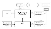
Abstract - This paper introduces a different approach to
the measurement of the time-of-flight of ultrasonic signals.
Frequency variation monitoring and recording is used to
determine accurately the arrival time of the ultrasonic signal.
A high speed Digital Signal Processor (D.S.P.) is used for
both: transmission and direct measurement of the frequency
of the incoming signal in every single period and with an
accuracy of about 0.1%. The proposed configuration offers
small size and low cost solution to displacement
measurements with a remarkable performance in terms of
accuracy, range and measurement time.

THE SYSTEM
The configuration of the proposed system is based on the
capabilities of accurate time measurement of modern microcontrollers.
The usual series of microcontrollers can not be
used in this application mainly because of their relatively
low frequency of operation (clock frequency) which affects
the accuracy of time measurement within one single period.
They can not offer the required fast and accurate frequency
measurement. A high performance system may therefore be
built only on a more powerful microcontroller. Larger
systems (personal computer type, etc) are avoided for
practical reasons; the overall measurement system should be
cost-effective and small sized.


More pdf


Ultrasonic Distance Sensor Implemented
with the Microcontroller Project

Linear measurement is a problem that a lot of
applications in the industrial and consumer market
segment have to contend with. Ultrasonic technology is
one of the solutions used by the industry. However, an
optimized balance between cost and features are a must
for almost all target applications. The ultrasonic distance
measurer (UDM) is used mainly when a non-contact
measurer is required. This is the type of solution this
document explains using a simple robot toy
implementation.

Description
The UDM is a demo that shows capability and performance
of the MC9RS08KA2 and the ultrasonic sensor to build a
distance measurer. Figure 2 shows the basic building block of
this project.


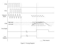
The firmware generates a 40 kHz burst signal. After the 10 cycle
burst is completed, a variable that measures the distance is
activated. This variable measures the time sound takes to rebound
and is used for distance calculation.

The burst signal goes to the ultrasonic transmitter (US Tx) and is
transmitted as ultrasound through the air Figure 2. When the wave
is reflected off an object, this wave is captured by the ultrasonic
receiver (US Rx.) This received signal is amplified because it
attenuates as it travels. Afterwards, the signal goes back to the
microcontroller unit (MCU), filters it and calculates the distance.
A 40 kHz interrupt is generated by the timer in the MCU. To
perform this, the keyboard interrupt (KBI) is enabled and detects
the external signal. Every time the MCU is interrupted the counter
is increased by three. And the variable used as a counter is
decreased by one for the entrances to the modulus timer module
(MTIM) interrupt service routine (ISR). When this variable is bigger
than eight the ECHO signal is activated. The distance variable is then
set to 0. Refer to Figure 3 for timing diagram. For detailed information
about the firmware see Figure 3.


read more "Ultrasonic Distance Sensor with the Microcontroller Project"

Thursday, April 15, 2010

Schematic Arduino Autopilot Control

Arduino Autopilot Control Project

ArduPilot is a full-featured autopilot based on the Arduino open-source hardware platform. It is a custom PCB with an embedded processor (ATMega168) combined with circuitry to switch between RC control and autopilot control (that's the multiplexer/failsafe, otherwise known as a "MUX"). This controls navigation (following GPS waypoints) and altitude by controlling the rudder and throttle. These components are all open source. This autopilot is fully programmable and can have any number of GPS waypoints (including altitude) and It uses infrared (thermopile) sensors for stabilization and GPS for navigation.

microcontroller auto pilot project

tag : Arduino project, Auto Pilot Control, Embedded project src

read more "Schematic Arduino Autopilot Control"