Accurate Ultrasonic Distance Measurement Project
Abstract - This paper introduces a different approach to
the measurement of the time-of-flight of ultrasonic signals.
Frequency variation monitoring and recording is used to
determine accurately the arrival time of the ultrasonic signal.
A high speed Digital Signal Processor (D.S.P.) is used for
both: transmission and direct measurement of the frequency
of the incoming signal in every single period and with an
accuracy of about 0.1%. The proposed configuration offers
small size and low cost solution to displacement
measurements with a remarkable performance in terms of
accuracy, range and measurement time.
THE SYSTEM
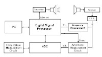
The configuration of the proposed system is based on the
capabilities of accurate time measurement of modern microcontrollers.
The usual series of microcontrollers can not be
used in this application mainly because of their relatively
low frequency of operation (clock frequency) which affects
the accuracy of time measurement within one single period.
They can not offer the required fast and accurate frequency
measurement. A high performance system may therefore be
built only on a more powerful microcontroller. Larger
systems (personal computer type, etc) are avoided for
practical reasons; the overall measurement system should be
cost-effective and small sized.

More pdf
Ultrasonic Distance Sensor Implemented
with the Microcontroller Project
Linear measurement is a problem that a lot of
applications in the industrial and consumer market
segment have to contend with. Ultrasonic technology is
one of the solutions used by the industry. However, an
optimized balance between cost and features are a must
for almost all target applications. The ultrasonic distance
measurer (UDM) is used mainly when a non-contact
measurer is required. This is the type of solution this
document explains using a simple robot toy
implementation.
Description
The UDM is a demo that shows capability and performance
of the MC9RS08KA2 and the ultrasonic sensor to build a
distance measurer. Figure 2 shows the basic building block of
this project.

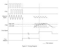
The firmware generates a 40 kHz burst signal. After the 10 cycle
burst is completed, a variable that measures the distance is
activated. This variable measures the time sound takes to rebound
and is used for distance calculation.
The burst signal goes to the ultrasonic transmitter (US Tx) and is
transmitted as ultrasound through the air Figure 2. When the wave
is reflected off an object, this wave is captured by the ultrasonic
receiver (US Rx.) This received signal is amplified because it
attenuates as it travels. Afterwards, the signal goes back to the
microcontroller unit (MCU), filters it and calculates the distance.
A 40 kHz interrupt is generated by the timer in the MCU. To
perform this, the keyboard interrupt (KBI) is enabled and detects
the external signal. Every time the MCU is interrupted the counter
is increased by three. And the variable used as a counter is
decreased by one for the entrances to the modulus timer module
(MTIM) interrupt service routine (ISR). When this variable is bigger
than eight the ECHO signal is activated. The distance variable is then
set to 0. Refer to Figure 3 for timing diagram. For detailed information
about the firmware see Figure 3.


No comments:
Post a Comment