Remote sensor sends data via mains supply, Temperature range: 00.0 to 99.9 °C
This circuit is intended for precision centigrade temperature measurement, with a transmitter section converting to frequency the sensor's output voltage, which is proportional to the measured temperature. The output frequency bursts are conveyed into the mains supply cables. The receiver section counts the bursts coming from mains supply and shows the counting on three 7-segment LED displays. The least significant digit displays tenths of degree and then a 00.0 to 99.9 °C range is obtained. Transmitter-receiver distance can reach hundred meters, provided both units are connected to the mains supply within the control of the same light-meter.
Transmitter circuit operation:
IC1 is a precision centigrade temperature sensor with a linear output of 10mV/°C driving IC2, a voltage-frequency converter. At its output pin (3), an input of 10mV is converted to 100Hz frequency pulses. Thus, for example, a temperature of 20°C is converted by IC1 to 200mV and then by IC2 to 2KHz. Q1 is the driver of the power output transistor Q2, coupled to the mains supply by L1 and C7, C8.
Circuit diagram:

R1 = 100K 1/4W Resistors
R2 = 47R 1/4W Resistor
R3 = 100K 1/4W Resistors
R4 = 5K 1/2W Trimmer Cermet
R5 = 12K 1/4W Resistor
R6 = 10K 1/4W Resistor
R7 = 6K8 1/4W Resistor
R8 = 1K 1/4W Resistors
R9 = 1K 1/4W Resistors
C1 = 220nF 63V Polyester Capacitor
C2 = 10nF 63V Polyester Capacitor
C3 = 1µF 63V Polyester Capacitor
C4 = 1nF 63V Polyester Capacitors
C5 = 2n2 63V Polyester Capacitor
C6 = 1nF 63V Polyester Capacitors
C7 = 47nF 400V Polyester Capacitors
C8 = 47nF 400V Polyester Capacitors
C9 = 1000µF 25V Electrolytic Capacitor
D1 = 1N4148 75V 150mA Diode
D2 = 1N4002 100V 1A Diodes
D3 = 1N4002 100V 1A Diodes
D4 = 5mm. Red LED
IC1 = LM35 Linear temperature sensor IC
IC2 = LM331 Voltage-frequency converter IC
IC3 = 78L06 6V 100mA Voltage regulator IC
Q1 = BC238 25V 100mA NPN Transistor
Q2 = BD139 80V 1.5A NPN Transistor
T1 = 220V Primary, 12+12V Secondary 3VA Mains transformer
PL = Male Mains plug & cable
L1 = Primary (Connected to Q2 Collector): 100 turns
Secondary: 10 turns
Wire diameter: O.2mm. enameled
Plastic former with ferrite core. Outer diameter: 4mm.
Receiver circuit operation:
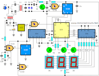
The frequency pulses coming from mains supply and safely insulated by C1, C2 & L1 are amplified by Q1; diodes D1 and D2 limiting peaks at its input. Pulses are filtered by C5, squared by IC1B, divided by 10 in IC2B and sent for the final count to the clock input of IC5. IC4 is the time-base generator: it provides reset pulses for IC1B and IC5 and enables latches and gate-time of IC5 at 1Hz frequency. It is driven by a 5Hz square wave obtained from 50Hz mains frequency picked-up from T1 secondary, squared by IC1C and divided by 10 in IC2A. IC5 drives the displays' cathodes via Q2, Q3 & Q4 at a multiplexing rate frequency fixed by C7. It drives also the 3 displays' paralleled anodes via the BCD-to-7 segment decoder IC6. Summing up, input pulses from mains supply at, say, 2KHz frequency, are divided by 10 and displayed as 20.0°C.
Circuit diagram:
This circuit is intended for precision centigrade temperature measurement, with a transmitter section converting to frequency the sensor's output voltage, which is proportional to the measured temperature. The output frequency bursts are conveyed into the mains supply cables. The receiver section counts the bursts coming from mains supply and shows the counting on three 7-segment LED displays. The least significant digit displays tenths of degree and then a 00.0 to 99.9 °C range is obtained. Transmitter-receiver distance can reach hundred meters, provided both units are connected to the mains supply within the control of the same light-meter.
Transmitter circuit operation:
IC1 is a precision centigrade temperature sensor with a linear output of 10mV/°C driving IC2, a voltage-frequency converter. At its output pin (3), an input of 10mV is converted to 100Hz frequency pulses. Thus, for example, a temperature of 20°C is converted by IC1 to 200mV and then by IC2 to 2KHz. Q1 is the driver of the power output transistor Q2, coupled to the mains supply by L1 and C7, C8.
Circuit diagram:

Transmitter parts:
R1 = 100K 1/4W Resistors
R2 = 47R 1/4W Resistor
R3 = 100K 1/4W Resistors
R4 = 5K 1/2W Trimmer Cermet
R5 = 12K 1/4W Resistor
R6 = 10K 1/4W Resistor
R7 = 6K8 1/4W Resistor
R8 = 1K 1/4W Resistors
R9 = 1K 1/4W Resistors
C1 = 220nF 63V Polyester Capacitor
C2 = 10nF 63V Polyester Capacitor
C3 = 1µF 63V Polyester Capacitor
C4 = 1nF 63V Polyester Capacitors
C5 = 2n2 63V Polyester Capacitor
C6 = 1nF 63V Polyester Capacitors
C7 = 47nF 400V Polyester Capacitors
C8 = 47nF 400V Polyester Capacitors
C9 = 1000µF 25V Electrolytic Capacitor
D1 = 1N4148 75V 150mA Diode
D2 = 1N4002 100V 1A Diodes
D3 = 1N4002 100V 1A Diodes
D4 = 5mm. Red LED
IC1 = LM35 Linear temperature sensor IC
IC2 = LM331 Voltage-frequency converter IC
IC3 = 78L06 6V 100mA Voltage regulator IC
Q1 = BC238 25V 100mA NPN Transistor
Q2 = BD139 80V 1.5A NPN Transistor
T1 = 220V Primary, 12+12V Secondary 3VA Mains transformer
PL = Male Mains plug & cable
L1 = Primary (Connected to Q2 Collector): 100 turns
Secondary: 10 turns
Wire diameter: O.2mm. enameled
Plastic former with ferrite core. Outer diameter: 4mm.
Receiver circuit operation:
The frequency pulses coming from mains supply and safely insulated by C1, C2 & L1 are amplified by Q1; diodes D1 and D2 limiting peaks at its input. Pulses are filtered by C5, squared by IC1B, divided by 10 in IC2B and sent for the final count to the clock input of IC5. IC4 is the time-base generator: it provides reset pulses for IC1B and IC5 and enables latches and gate-time of IC5 at 1Hz frequency. It is driven by a 5Hz square wave obtained from 50Hz mains frequency picked-up from T1 secondary, squared by IC1C and divided by 10 in IC2A. IC5 drives the displays' cathodes via Q2, Q3 & Q4 at a multiplexing rate frequency fixed by C7. It drives also the 3 displays' paralleled anodes via the BCD-to-7 segment decoder IC6. Summing up, input pulses from mains supply at, say, 2KHz frequency, are divided by 10 and displayed as 20.0°C.
Circuit diagram:
Receiver Circuit Diagram
Receiver Parts:
R1 = 100K 1/4W Resistor
R2 = 1K 1/4W Resistor
R3 = 12K 1/4W Resistors
R4 = 12K 1/4W Resistors
R5 = 47K 1/4W Resistor
R6 = 12K 1/4W Resistors
R8 = 12K 1/4W Resistors
R9-R15=470R 1/4W Resistors
R16 = 680R 1/4W Resistor
C1 = 47nF 400V Polyester Capacitors
C2 = 47nF 400V Polyester Capacitors
C3 = 1nF 63V Polyester Capacitors
C4 = 10nF 63V Polyester Capacitor
C7 = 1nF 63V Polyester Capacitors
C5 = 220nF 63V Polyester Capacitors
C6 = 220nF 63V Polyester Capacitors
C8 = 1000µF 25V Electrolytic Capacitor
C9 = 100pF 63V Ceramic Capacitor
C10 = 220nF 63V Polyester Capacitors
D1 = 1N4148 75V 150mA Diodes
D2 = 1N4148 75V 150mA Diodes
D3 = 1N4002 100V 1A Diodes
D4 = 1N4002 100V 1A Diodes
D5 = 1N4148 75V 150mA Diodes
D6 = Common-cathode 7-segment LED mini-displays
D7 = Common-cathode 7-segment LED mini-displays
D8 = Common-cathode 7-segment LED mini-displays
IC1 = 4093 Quad 2 input Schmitt NAND Gate IC
IC2 = 4518 Dual BCD Up-Counter IC
IC3 = 78L12 12V 100mA Voltage regulator IC
IC4 = 4017 Decade Counter with 10 decoded outputs IC
IC5 = 4553 Three-digit BCD Counter IC
IC6 = 4511 BCD-to-7-Segment Latch/Decoder/Driver IC
Q1 = BC239C 25V 100mA NPN Transistor
Q2 = BC327 45V 800mA PNP Transistors
Q3 = BC327 45V 800mA PNP Transistors
Q4 = BC327 45V 800mA PNP Transistors
PL = Male Mains plug & cable
T1 = 220V Primary, 12+12V Secondary 3VA Mains transformer
L1 = Primary (Connected to C1 & C2): 10 turns
Secondary: 100 turns
Wire diameter: O.2mm. enameled
Plastic former with ferrite core. Outer diameter: 4mm.
Notes:
R1 = 100K 1/4W Resistor
R2 = 1K 1/4W Resistor
R3 = 12K 1/4W Resistors
R4 = 12K 1/4W Resistors
R5 = 47K 1/4W Resistor
R6 = 12K 1/4W Resistors
R8 = 12K 1/4W Resistors
R9-R15=470R 1/4W Resistors
R16 = 680R 1/4W Resistor
C1 = 47nF 400V Polyester Capacitors
C2 = 47nF 400V Polyester Capacitors
C3 = 1nF 63V Polyester Capacitors
C4 = 10nF 63V Polyester Capacitor
C7 = 1nF 63V Polyester Capacitors
C5 = 220nF 63V Polyester Capacitors
C6 = 220nF 63V Polyester Capacitors
C8 = 1000µF 25V Electrolytic Capacitor
C9 = 100pF 63V Ceramic Capacitor
C10 = 220nF 63V Polyester Capacitors
D1 = 1N4148 75V 150mA Diodes
D2 = 1N4148 75V 150mA Diodes
D3 = 1N4002 100V 1A Diodes
D4 = 1N4002 100V 1A Diodes
D5 = 1N4148 75V 150mA Diodes
D6 = Common-cathode 7-segment LED mini-displays
D7 = Common-cathode 7-segment LED mini-displays
D8 = Common-cathode 7-segment LED mini-displays
IC1 = 4093 Quad 2 input Schmitt NAND Gate IC
IC2 = 4518 Dual BCD Up-Counter IC
IC3 = 78L12 12V 100mA Voltage regulator IC
IC4 = 4017 Decade Counter with 10 decoded outputs IC
IC5 = 4553 Three-digit BCD Counter IC
IC6 = 4511 BCD-to-7-Segment Latch/Decoder/Driver IC
Q1 = BC239C 25V 100mA NPN Transistor
Q2 = BC327 45V 800mA PNP Transistors
Q3 = BC327 45V 800mA PNP Transistors
Q4 = BC327 45V 800mA PNP Transistors
PL = Male Mains plug & cable
T1 = 220V Primary, 12+12V Secondary 3VA Mains transformer
L1 = Primary (Connected to C1 & C2): 10 turns
Secondary: 100 turns
Wire diameter: O.2mm. enameled
Plastic former with ferrite core. Outer diameter: 4mm.
Notes:
- D6 is the Most Significant Digit and D8 is the Least Significant Digit.
- R16 is connected to the Dot anode of D7 to illuminate permanently the decimal point.
- Set the ferrite cores of both inductors for maximum output (best measured with an oscilloscope, but not critical).
- Set trimmer R4 in the transmitter to obtain a frequency of 5KHz at pin 3 of IC2 with an input of 0.5Vcc at pin 7 (a digital frequency meter is required).
- More simple setup: place a thermometer close to IC1 sensor, then set R4 to obtain the same reading of the thermometer in the receiver's display.
- Keep the sensor (IC1) well away from heating sources (e.g. Mains Transformer T1).
- Linearity is very good.
- Warning! Both circuits are connected to 230Vac mains, then some parts in the circuit boards are subjected to lethal potential! Avoid touching the circuits when plugged and enclose them in plastic boxes.


 Posts
Posts


