Sunday, August 22, 2010

Snake Robot Project

Anna Konda
The fire fighting snake robotAnna Konda was developed in order to demonstrate the SnakeFighter concept. The robot is to our knowledge the biggest and strongest snake robot in the world and also the first water hydraulic snake robot ever constructed.


Embedded control systemMicrocontrollers (AVR ATmega128) are used to control the motion of the joints of Anna Konda. A communication bus through the robot allows for communication between the microcontrollers and a dedicated controller in the head of the robot (the brain). The brain can communicate with an external computer through a wireless connection based on Bluetooth. This allows the robot to be remotely controlled by an operator.

http://www.sintef.no/Home/Information-and-Communication-Technology-ICT/Applied-Cybernetics/Projects/Our-snake-robots/Anna-Konda--The-fire-fighting-snake-robot/

Robot spy
can survive battlefield damageBentley and his colleague Siavash Haroun Mahdavi borrowed a trick from evolution to allow their robot to adapt to damage. The snakebot is made up of modular vertebral units that "snap" together to form a snake-like body (see graphic). Each unit contains three separate "muscles" running down its length. The muscles are made out of wires of a shape-memory alloy called nitinol, an alloy of nickel and titanium whose crystal structure shrinks when an electric current is applied to it. Usefully, it regains its original shape and length once the current is removed. To make the snakebot move in a particular direction, a current is applied to certain wires. When the current is removed, the wires spring back and the robot will jump forward.


http://www.newscientist.com/article/dn4075

Snakebot
Snakebots that are being developed will be able to independently dig in loose extraterrestrial soil, are smart enough to slither into cracks in a planet's surface, and are capable of planning routes over or around obstacles


http://www.nasa.gov/centers/ames/news/releases/2000/00images/snakebot/snakebot.html

Amphibious snake-like robot "ACM-R5"(2005-)
Sea snakes live in water, and even terrestrial snakes sometimes show swimming on water surface. In fact, the mechanism of snakes’ propulsion is almost same both in water and on ground. An amphibious snake-like robot ACM-R5 (Fig. 1) takes advantage of this fact. It can operate both on ground and in water undulating its long body (Fig. 2, Fig. 3).


The joint of ACM-R5 consists of an universal joint and bellows (Fig 4). It was developed on the basis of the previous model HELIX, which was designed for research of spirochete-like helical swimming. An universal joint plays a role of bones, and bellows do a role of an integument. ACM-R5 can form a smooth shape due to this joint structure, and it is important for effective locomotion. To be precise, the universal joint has one passive twist joint at the intersection point of two bending axis to prevent mechanical interference with bellows.


http://www-robot.mes.titech.ac.jp/robot/snake/acm-r5/acm-r5_e.html


Robot Snake Vedio

Cool Robot Snake
I want one of these! THINK IT'S FAKE? Check out Dr. Gavin Miller's site... http://www.snakerobots.com/... This is the S5 version of S1 thru S7. We HAVE the technology! Some of you younger puppies


Robotic Snake
A robotic snake swimming at the Odensee Robot Festival, August 2007


Slithertron - Robot Snake
Evolution of a Robotic Snake


SuperBot Sidewinder – Amazing


read more "Snake Robot Project"

Friday, August 13, 2010

Schematic AVR Rotating Led Display

Cool POV project : AVR Rotating Led Display


If you like Rotating LED Display project, check out Rotating Led Display project by Aki Korhonen. He made POV project using modified 8 cm fan and microcontroller AVR AT mega as main part. To control the led, the project use 74HC595D shift registers. Not only can display the text this Rotating Led display can also demonstrate drawing and playable Pong game. Check the video below,


tag: POV led display, rotating display, LED animation, AVR project (src)


read more "Schematic AVR Rotating Led Display"

Monday, August 2, 2010

Schematic PIC Cactus LED Display

LED Cactus Display PIC Project

LEDactus is LED display project that resemble Cactus. It used PIC microcontroller 18F1320 as controller of the LED. LEDactus is immobile and attempts to survive by creating a pleasant display. It can produce more complex and mesmerizing displays. And in the latest generations, a sense of touch is added to allow the LEDactus to interact with passersby.

term : LED display, electronic cactus, PIC project (src)

read more "Schematic PIC Cactus LED Display"

Tuesday, July 27, 2010

Compass Sensor with Microcontroller Project


INTERFACING AN ANALOG COMPASS TO AN EMBEDDEDCONTROLLER
AbstractThis paper describes the development of a compass sensing unit for use on a remotely operated vessel. The sensor determines the direction of the vessel’s path to aide the user in operating the boat wirelessly through a laptop. The system provides information tofacilitate tracking and controlling the boat when it is not easily seen by the operator. The selected compass, Dinsmore R1655 analog compass sensor, was used in conjunction ofan 8051 microcontroller to provide the necessary data. The system was able to read an analog value from the sensor and convert it to digital direction. The paper will describe the system design and present test results.


http://www.icee.usm.edu/icee/conferences/asee2007/
papers/630_INTERFACING_AN_ANALOG_COMPASS_TO_AN_EMBE.pdf

Microcontroller Design Final Project: Digital Compass
The goal of this project is to build a digital compass that displays both the direction and cardinal points on a television. Other functionalities were added to complement the sensor interface, such as, temperature display, magnetic declination input and disability option.


http://instruct1.cit.cornell.edu/courses/ee476/FinalProjects/s2004/ccw27/index.htm

Electronic Compass Design using KMZ51 and KMZ52
This paper describes how to realize electronic compass systems using the magnetoresistive Sensors KMZ51 and KMZ52 from Philips Semiconductors. Therefore, firstly an introduction to the characteristics of the earth´s magnetic field is given. In the following, the main building blocks of an electronic compass are shown, which are two sensor elements for measuring the x- and y-components of the earth field in the horizontal plane, a signalconditioning unit and a direction determination unit.

Functional block diagram of an electronic compass


http://www.nxp.com/acrobat_download/applicationnotes/AN00022_COMPASS.pdf


Autocalibration of an Electronic Compass for Augmented Reality
Abstract
Electronic compass is often used to provide the absoluteheading reference for tracking the user’s head and handsin Virtual Reality (VR) and Augmented Reality (AR),especially for outdoor AR applications. However,compass is vulnerable to environment magnetismdisturbance. Existing compass calibration methodsrequire complex steps and true heading reference whichis often impossible to be obtained in outdoor ARapplications, and is useful only when compass is inhorizontal plane. An autocalibration method without theneed of heading reference and redundant Sensors isproposed in this paper. First the compass error modelbased on physical principle is presented, then thealgorithm to calculate the compensation coefficients witha set of sample measurements of the Sensors in thecompass is described. Because the influence of theenvironmental disturbance has been effectivelycompensated, the calibrated compass can providedaccurate heading even when it is under large tilt attitude.

http://csdl2.computer.org/comp/proceedings/ismar/2005/2459/00/24590182.pdf


3-AXIS COMPASS REFERENCE DESIGN with Microcontroller Circuit


The HMC1052 two-axis magnetic sensor contains two Anisotropic Magneto-Resistive (AMR) sensor elements in a singleMSOP-10 package. Each element is a full wheatstone bridge sensor that varies the resistance of the bridge magnetoresistorsin proportion to the vector magnetic field component on its sensitive axis. The two bridges on the HMC1052 areorientated orthogonal to each other so that a two-dimensional representation of an magnetic field can be measured. Thebridges have a common positive bridge power supply connection (Vb); and with all the bridge ground connections tiedtogether, form the complete two-axis magnetic sensor. Each bridge has about an 1100-ohm load resistance, so eachbridge will draw several milli-amperes of current from typical digital power supplies. The bridge output pins will present adifferential output voltage in proportion to the exposed magnetic field strength and the amount of voltage supply acrossthe bridge. Because the total earth’s magnetic field strengthis very small (~0.6 gauss), each bridge’s vector component ofthe earth’s field will even be smaller and yield only a couple milli-volts with nominal bridge supply values. Aninstrumentation amplifier circuit; to interface with the differential bridge outputs, and to amplify the sensor signal byhundreds of times, will then follow each bridge voltage output.

http://www.ssec.honeywell.com/magnetic/datasheets/hmc1055.pdf
read more "Compass Sensor with Microcontroller Project"

Tuesday, July 13, 2010

Schematic One Motor Walker Robot Without uC

Walker Robot Without uC
Robot is interesting electronic project. We often see that robot project need a microcontroller as main processor. But if you don't have any programming skill yet, don't worry, you can build one motor walker robot by Jerome Demers. Yes the it's a walker robot without a microcontroller. The robot is base on the principal of B.E.A.M robotics! Building simple and elegant robot inspired by insect.

See the robot in action


via circuitlake

read more "Schematic One Motor Walker Robot Without uC"

Monday, July 5, 2010

Robot Arm Project and Robot ArmVedio

AROBOT ARM TUTORIAL
The robot arm is probably the most mathematically complex robot you could ever build. As such, this tutorial can't tell you everything you need to know. Instead, I will cut to the chase and talk about the bare minimum you need to know to build an effective robot arm.


Design and Application of a 3 DOF Bionic Robot Arm
High efforts are put in the mechanical design of industrial manipulators to obtain high position accuracy using rigid joint actuators and rigid arms resulting in heavy masses of arms. For safety reasons, they can only be used in environments strictly separated from humans. Thus they stand in remarkable contrast to animals and humans with their much better relationship from payload to arm weight, and its concurrent high movement quality by "intelligent" control.


Robotic arm
I present the results, hoping it will be useful to other people who are also interested. This robotic arm is a little demonstration, it uses stock servo-motors normally used in RC models, and is controlled from a pc, attached with a serial cable.


Computerized wireless Pick n Place Robot
this is the most advance version of “Pick n Place Robot” perhaps and most popular and widely used in recent industries. A person from a remote place can comfortably control the motion of robotic arm without any wire connection.


RoboSim- A Simple 6-DOF Robot Manipulator Simulation System
RoboSim is a very simple simulation system for a 6 degres of freedom robot manipulator. The basic functions of the control panel are to move the manipulator either in joint coordinates or in cartesian coordinates. It is also possible, to change the view position or change length and color of the links. Joint weights may be set, in order to favor movement of individual joints versus others


sbcRobotics
torsoHead LeftArm stepper motors showing, stepper motor control board, and cardboard hand or fingers. The cardboard fingers are place holders and have been cut to the same proportions as a human hand. This is needed to gauge the real distance for the arm's reach. The fingers will be replaced with the finished hand.


http://www.sbcrobotics.com/sbcRoboticsTorsoHead.htm
Atlas II Robotic SystemATLAS II is a complete robotic system consisting of the robot arm, power supplies, and control microcomputer.


Robot Arm Made Vedio

Robot Arm on How it's Made


Robotic Arm Made Out of Recycled Materials (Build)


My first Robot Arm


Robotic Arm With Four Degree Of Freedom


articulate robotic arm gripper mechanism


Robot arm with stepper motor


Robot arm simulation in Solidworks2009


read more "Robot Arm Project and Robot ArmVedio"

Wednesday, June 30, 2010

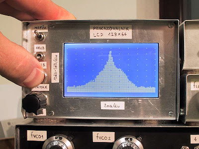
Schematic PIC LCD Oscilloscope for Spectrum Analyzers

PIC LCD Oscilloscope for Spectrum Analyzers
This is simple and inexpensive LCD oscilloscope for spectrum analyzer display. The project use PIC 16F876A as main processor. Although a small LCD screen is not as good as analog oscilloscope, a LCD oscilloscope may be very useful in field measurements, for battery operation or you need different measurement at the same time along with oscilloscope.

The 80dB scale of this LCD oscilloscope can be adjusted with the two trimmers providing the reference voltages to the A/D converter. The operation of the LCD oscilloscope is slightly different between the 80dB mode and the 40dB mode. In the 80dB mode, the trace is always visible and saturates on the bottom or top of screen. In the 40dB mode, the trace runs out of the screen and only the central part of the original 80dB scale is displayed. This project designed by Matjaz Vidmar.

Download
Source code, documentation and schematic

tags : LCD, Oscilloscope, Spectrum Analyzer, PIC, microcontroller, project src

read more "Schematic PIC LCD Oscilloscope for Spectrum Analyzers"