Wednesday, April 7, 2010

Schematic AVR Nikon Camera Remote Control

Nikon Camera Remote Control Microcontroller project

This is an IR remote control for Nikon cameras. The circuit project is very simple: an ATtiny13V, button, transistor, resistor, IR diode and 3V battery. You can also connect the IR diode directly to the ATtiny13V, but that will limit the LED current and therefore the range. The project is compatible with the Nikon ML-L3 remote control. Supported cameras include: D40, D40X, D50, D60, D70, D70s, D80, and Coolpix 8400 8800. This project created by Dick Streefland

Download:
Schematic and source code

Tag: Remote control, Camera RC, AVR project (src)


read more "Schematic AVR Nikon Camera Remote Control"

Monday, April 5, 2010

Schematic AVR Based Diode Temperature Meter

Temperature Meter
This is Multi channel diode temperature meter project with Microcontroller AVR AT90S2333 as main controller. It can be use to replace thermister temperature meter.

Front end of the temperature sensor and amplifier circuit consists of constant current. Approximately a constant current of 63µA sensor (diode) in the sink, a diode voltage drop of 3-fold amplification and A / D converter (10bit, 3.3V/fs) type. Drift in this block is the main cause of measurement error, the components must be selected as the low temperature drift.

Where an adjustment is not analog, EEPROM calibration parameters are calculated from the temperature to make sure that you store in it. The calibration process is required for proper equipment such as computer terminals instead of the driver. Some cases, ISP via cable (N81, 38.4kbps) has been to enter the calibration mode is turned on and connected.

Download:
Schematic and source code

Tag: Temperature Meter, Microcontroller AVR project, electronic project (src)


read more "Schematic AVR Based Diode Temperature Meter"

Line Tracking Robot Project

Two Inexpensive Line Tracking Sensors for the MIT
Handy Board Microcontroller
1.Theory of Operation
A line sensor in its simplest form is a sensor capable of detecting
a contrast between adjacent surfaces, such as difference in color
, roughness, or magnetic properties, for example. The simplest
would be detecting a difference in color, for example black and
white surfaces. Using simple optoelectronics, such as infrared
photo-transistors, color contrast can easily be detected . Infrared
emitter/detectors or photo-transistors are inexpensive (usually
under $1 per sensor) and are easy to interface to a microcontroller.
In addition, standard red LEDs and Cds photocells work well too
and fall in the same price range as the infrared photo-transistors.


2. Construction
3. Sample Code
Sample Interactive C Code for the Handy
Board Microcontroller
4. Final Design of the Sensor and Robot
5. Performance

more


Line Tracking Robot Project
This project is based on the MOVIT/OWIKIT LINE TRACKER
kit. Each group of three students is provided with one kit.
However, to make the project more meaningful, each group
will construct and test each of the electrical subsystems of the
robot on a breadboard and test it. After the entire system is
put together in this fashion and its operation understood, each
group will also put the pre-wired kit together and observe its
behavior.


more

Line Follower ROBOT
I designed my Robot, which use two motors control rear wheels
and the single front wheel is free. It has 4-infrared Sensors on
the bottom for detect black tracking tape, when the Sensors
detected black color, output of comparator, LM324 is low logic
and the other the output is high.


Software
Software for write to AT89C2051 is robot1.hex ,which was
written by C-language ,the source code is robot1.ccompiled
by using MC51 in TINY model with my start up code
robot.asm .
more


Sandwich, an Easy to Build Robot That Follows Lines


I've built four Sandwich robots so far. Three of them are pictured
above (Sandwich, Blue Sandwich, and Red Sandwich) and one
robot was given away (Green Sandwich). The robots are named
for the color of the m&m's mini mega candy tube that connects
their motors together.
style="font-family:arial;">
read more "Line Tracking Robot Project"

Saturday, April 3, 2010

Robot Line Tracking Sensors Circuit

The infrared emitter and detector Sensors
Figure 4. Circuit diagram for the infrared emitter/detector line
sensor for the MIT Handy Board. If you plan on making the
sensor from color LEDs and Cds photocells, replace the IR
emitter with a red LED and the IR detector with a Cds photocell.
Click here for a circuit diagram if the sensor is used with other
microcontrollers. Note the subtle difference in the way the IR
detector is configured for this design.


more

Building the sensor
Here is the electronic circuit of the LDR based line sensor we
used in our robots in the Robocon 2007 competition. As you
can see it is composed of eight cells, each one resembling the
cell in figure 3.B. There are many reasons to choose to build
a sensor with exactly eight cells, no more, no less: Eight can
provide enough precision, it connects directly to one port of
the microcontroller, and is represented by one single Byte of
data, making it easier to implement in the programming and
in the memory of an 8 bit microcontroller.


more

Photo Interrupters
The LED emits infrared radiation. If the Photo Interrupter passes
over a white surface, the infrared light is reflected back and is
detected by the phototransistor. Let us assume that this is the
case for the right (shown in red) photo interrupter assembly. The
result is that the emitter-collector resistance drops and a large
current flows through the red 27k resistor. This created a large
voltage drop across this resistor and VR is reduced to near zero.
If at the same time, the left photo interrupter assembly (shown
in blue) is over the black line, the radiation is not reflected back
to the phototransistor and the emitter-collector resistance
remains high. This results in a small current through the blue 27k
resistor. The resulting small voltage drop across this resistor
leads to a high value of ~9 V for VL. We send these two voltages
to a comparator, which then makes one of the two wheels of the
robot rotate in such a fashion that it turns to the left.


read more "Robot Line Tracking Sensors Circuit"

Friday, April 2, 2010

Digital Light Sensor to MICROCONTROLLER Circuit


ISL29001


The ISL29001 is an integrated ambient light sensor with
ADC and I2C interface. With a spectral sensitivity curve
matched to that of the human eye, the ISL29001 provides
15-bit effective resolution while rejecting 50Hz and 60Hz
flicker caused by artificial light sources.
In normal operation, the ISL29001 consumes less than
300µA of supply current. A software power-down mode
controlled via the I2C interface disables all but the I2C
interface. A power-down pin is also provided, which reduces
power consumption to less than 1µA.
The ISL29001 includes an internal oscillator, which provides
100ms automatic integration periods, or can be externally
timed by I2C commands. Both the internal timing and the
illuminance resolution can be adjusted with an external
resistor.

ISL29001 datasheet pdf


Microcontroller Advanced Kit - Light Sensor Project

This tutorial shows how to set up a microcontroller based
system that converts a signal from a light sensor to a 6 bit
digital value. This value can be used by the microcontroller,
perhaps for a robotic controller, or as in this tutorial, sent to
the PC. It uses the AT89C2051 microcontroller to collect
data and send it to the PC. A MAX232CPE chip is used to
convert the signals from and to RS232 levels for sending
and receiving through the serial port. The 2051 microcontroller
has a built in analog comparator that is used to make a
simple analog to digital converter to convert the light sensor
output to a digital value.


read more "Digital Light Sensor to MICROCONTROLLER Circuit"

Schematic Small USB Device Charger

USB Battery charger

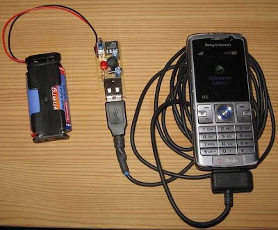
This advance tiny USB battery powered charger is handy tools for your need. You can use it to charge almost all devices which are charged via USB, like iPods or mobile phones, with only two AA-Cells. The Most important compenent of the cicuit LT1301. This is a small step up converter for to build switching mode power supplys with only a few external components.

Download :
Schematic and document

tag : USB Charger, Battery Powered Charger, Small Charger (src)


read more "Schematic Small USB Device Charger"

Thursday, April 1, 2010

Light Sensor Circuit 2


Light-controlled pond pump
This circuit was constructed to control the pump in a garden
pond, so that it automatically turns on at dawn and off again
at dusk. Not only does this mean that we don’t have to get
cold and wet when turning the pump on or off manually but
it’s also one less job for our kind neighbours when we go
away on holidays!


more

Light Detection Using A Phototransistor and Voltage
Comparator
This page describes an example project that turns on a red
LED when light is dim and a green LED when light is bright.
Or more to the point, changes color when objects (such as
a fan blade) pass in front of it.Because the lighting required

to enable either LED is controlled by individual potentiometers,

they can be set such that either, neither, or both LEDs turn on.

That is, the red LED doesn't have to turn on simply because the

green LED turned off.


more

Internals of RCX Input Ports and Sensors
When it comes to the active Sensors these are much more
complicated inside as can be seen from the figures 4 to 7.
There is however still a simple relationship between the raw
value measured and the sensor resistance if the A/D
conversion takes place with no power is supplied to the


more


Laser Pointer Triggered On/Off Switch
Remote control is commonly performed with either modulated
infrared emitters or radio-frequency wireless transmitters.
During a boring presentation, it occurred to me that the
presenter could control a slide show by aiming their laser
pointer at a list of commands with bullet-point targets.
Alternatively, someone lying in bed could set the clock
alarm/snooze (across the room) or turn off lights by simply
aiming the laser dot at the correct spot on the desired object.


read more "Light Sensor Circuit 2"