Monday, December 31, 2012

Control Variable DC Power Supply With LM317

This DC power supply circuit is adjustable using IC Voltage Regulator LM317. LM317 is a versatile and highly efficient 1.2-37V voltage regulatorthat can provide up to 1.5A of current with a large heat sink. It'sideal for just about any application. This was my first workbench powersupply and I still use it.

Since LM317 is protectedagainst short-circuit, no fuse is necessary. Thanks to automaticthermal shutdown, it will turn off if heating excessively. All in all,a very powerful (and affordable!) package, indeed.

Although voltage regulator LM317 is capable of delivering up to 37V, the DC power supplyoutput circuit here is limited to 25V for the sake of safety andsimplicity. Any higher output voltage would require additionalcomponents and a larger heat sink.

Make sure that theinput voltage is at least a couple of Volts higher than the desiredoutput. It's OK to use a trim-pot if you're building a fixed-voltagesupply.

Problems:
Follow all the safety precautions when working with mains voltage. Insulate all connections on the transformer.
read more "Control Variable DC Power Supply With LM317"

Friday, December 28, 2012

Control 6A, 5 Volt Power Supply

The standard variable voltage regulator type LM150 is fairly easily available, but at times its out, which is limited to about 3 amperes, may prove to e a limiting factor to its utility, nut the simple modification describe here allows the to be enhanced to about 6 amperes. The circuit has inbuilt safe area protection and thermal overload protection.The circuit has been tested for lone regulation of the order of about 0.01% volt and load regulation of about 0.1% volt.
The circuit works on principle similar to the compact 10A power supplies. The two LM150 regulators are wired in parallel mode with  IC3 which controls them. The output voltage is given by the relation
Vout=1,25x(1+R5/R4) volts. The input voltage may lie anywhere in the range of 12 to 30 volts.

The IC must be adequately heat sinked in order to obtain full output current all over the operative temperature range 

The circuit 6A, 5 volt Power Supply
read more "Control 6A, 5 Volt Power Supply"

Control 32W HiFi Amplifier circuit based on TDA2050

This is a High Fidelify (Hi-Fi) amplifier circuit based on single IC TDA205. This is a mono channel audio amplifier. You need to build the same circuit for stereo channel.


TDA2050 Description:
The TDA 2050 is a monolithic integrated circuitin Pentawatt package, intended for use as an audio class AB audioamplifier. Thanks to its high power capability the TDA2050 is able toprovide up to 35W true rms power into 4 ohm load @ THD =10%, VS = ±18V,f = 1KHz and up to 32W into 8ohm load @ THD = 10%, VS = ±22V, f = 1KHz.Moreover, the TDA 2050 delivers typically 50W music power into 4 ohmload over 1 sec at VS=22.5V, f = 1KHz.
The high power and verylow harmonic and crossover distortion (THD = 0.05% typ, @ VS = ±22V, PO= 0.1 to 15W, RL=8ohm, f = 100Hz to 15KHz) make the device mostsuitable for both HiFi and high class TV sets.
read more "Control 32W HiFi Amplifier circuit based on TDA2050"

Thursday, December 27, 2012

Control High Current Regulated Supply

The high current regulator below uses an additional winding or a separate transformer to supply power for the LM317 regulator so that the pass transistors can operate closer to saturation and improve efficiency. For good efficiency the voltage at the collectors of the two parallel 2N3055 pass transistors should be close to the output voltage. The LM317 requires a couple extra volts on the input side, plus the emitter/base drop of the 3055s, plus whatever is lost across the (0.1 ohm) equalizing resistors (1volt at 10 amps), so a separate transformer and rectifier/filter circuit is used that is a few volts higher than the output voltage. The LM317 will provide over 1 amp of current to drive the bases of the pass transistors and assumings a gain of 10 the combination should deliver 15 amps or more. The LM317 always operates with a voltage difference of 1.2 between the output terminal and adjustment terminal and requires a minimum load of 10mA, so a 75 ohm resistor was chosen which will draw (1.2/75 = 16mA). This same current flows through the emitter resistor of the 2N3904 which produces about a 1 volt drop across the 62 ohm resistor and 1.7 volts at the base. The output voltage is set with the voltage divider (1K/560) so that 1.7 volts is applied to the 3904 base when the output is 5 volts. For 13 volt operation, the 1K resistor could be adjusted to around 3.6K. The regulator has no output short circuit protection so the output probably should be fused.
read more "Control High Current Regulated Supply"

Control TDA7295, 80W Audio Amplifier

Below is a 80W amplifier circuit is constructed by using a power ICTDA7295. With a very simple design, makes this circuit very easy tobuild. TDA7295 has many features to support your audio system, the most important is that the IC has very low distortion and very low noise feature.


The TDA7295 is a monolithic integrated circuit in Multiwatt15package, intended for use as audio class AB amplifier in Hi-Fi fieldapplications such as home theatre and topclass TV. The wide voltagerange and to the high out current capability make the TDA7295 able tosupply the highest power into both 4W and 8W loads even in presence ofpoor supply regulation, with high Supply Voltage Rejection.
The built in muting function with turn on delay simplifies the remote operation avoiding switching on-off noises.
read more "Control TDA7295, 80W Audio Amplifier"

Wednesday, December 26, 2012

Control 10W Audio Amplifier circuit based on TDA1910

Simple and cheap, that's the advantage of this circuit. Although the output power is not high but audio quality is good, because TDA1910 has a very low noise feature. This circuit suitable for use as a student project.

About TDA1910:
The TDA1910 is a monolithic integrated circuit in MULTIWATT® package, intended for use in Hi-Fi audio power applications, as high quality TV sets.
TheTDA 1910 meets the DIN 45500 (d = 0.5%) guaranteed output power of 10Wwhen used at 24V/4W. At 24V/8W the output power is 7W min.
TDA1910 Features:
  • muting facility
  • protection against chip over temperature
  • very low noise
  • high supply voltage rejection
  • low “switch-on” noise.
read more "Control 10W Audio Amplifier circuit based on TDA1910"

Tuesday, December 25, 2012

Control Digital Remote Thermometer Circuit With Receiver and Transmitter

Remote sensor sends data via mains supply, Temperature range: 00.0 to 99.9 °C

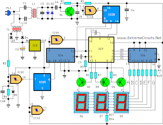
This circuit is intended for precision centigrade temperature measurement, with a transmitter section converting to frequency the sensor's output voltage, which is proportional to the measured temperature. The output frequency bursts are conveyed into the mains supply cables. The receiver section counts the bursts coming from mains supply and shows the counting on three 7-segment LED displays. The least significant digit displays tenths of degree and then a 00.0 to 99.9 °C range is obtained. Transmitter-receiver distance can reach hundred meters, provided both units are connected to the mains supply within the control of the same light-meter.

Transmitter circuit operation:

IC1 is a precision centigrade temperature sensor with a linear output of 10mV/°C driving IC2, a voltage-frequency converter. At its output pin (3), an input of 10mV is converted to 100Hz frequency pulses. Thus, for example, a temperature of 20°C is converted by IC1 to 200mV and then by IC2 to 2KHz. Q1 is the driver of the power output transistor Q2, coupled to the mains supply by L1 and C7, C8.

Circuit diagram:

Transmitter parts:


R1 = 100K 1/4W Resistors
R2 = 47R 1/4W Resistor
R3 = 100K 1/4W Resistors
R4 = 5K 1/2W Trimmer Cermet
R5 = 12K 1/4W Resistor
R6 = 10K 1/4W Resistor
R7 = 6K8 1/4W Resistor
R8 = 1K 1/4W Resistors
R9 = 1K 1/4W Resistors

C1 = 220nF 63V Polyester Capacitor
C2 = 10nF 63V Polyester Capacitor
C3 = 1µF 63V Polyester Capacitor
C4 = 1nF 63V Polyester Capacitors
C5 = 2n2 63V Polyester Capacitor
C6 = 1nF 63V Polyester Capacitors
C7 = 47nF 400V Polyester Capacitors
C8 = 47nF 400V Polyester Capacitors
C9 = 1000µF 25V Electrolytic Capacitor

D1 = 1N4148 75V 150mA Diode
D2 = 1N4002 100V 1A Diodes
D3 = 1N4002 100V 1A Diodes
D4 = 5mm. Red LED

IC1 = LM35 Linear temperature sensor IC
IC2 = LM331 Voltage-frequency converter IC
IC3 = 78L06 6V 100mA Voltage regulator IC

Q1 = BC238 25V 100mA NPN Transistor
Q2 = BD139 80V 1.5A NPN Transistor
T1 = 220V Primary, 12+12V Secondary 3VA Mains transformer
PL = Male Mains plug & cable
L1 = Primary (Connected to Q2 Collector): 100 turns
Secondary: 10 turns
Wire diameter: O.2mm. enameled
Plastic former with ferrite core. Outer diameter: 4mm.

Receiver circuit operation:

The frequency pulses coming from mains supply and safely insulated by C1, C2 & L1 are amplified by Q1; diodes D1 and D2 limiting peaks at its input. Pulses are filtered by C5, squared by IC1B, divided by 10 in IC2B and sent for the final count to the clock input of IC5. IC4 is the time-base generator: it provides reset pulses for IC1B and IC5 and enables latches and gate-time of IC5 at 1Hz frequency. It is driven by a 5Hz square wave obtained from 50Hz mains frequency picked-up from T1 secondary, squared by IC1C and divided by 10 in IC2A. IC5 drives the displays' cathodes via Q2, Q3 & Q4 at a multiplexing rate frequency fixed by C7. It drives also the 3 displays' paralleled anodes via the BCD-to-7 segment decoder IC6. Summing up, input pulses from mains supply at, say, 2KHz frequency, are divided by 10 and displayed as 20.0°C.

Circuit diagram:
Receiver Circuit Diagram
Receiver Parts:

R1 = 100K 1/4W Resistor
R2 = 1K 1/4W Resistor
R3 = 12K 1/4W Resistors
R4 = 12K 1/4W Resistors
R5 = 47K 1/4W Resistor
R6 = 12K 1/4W Resistors
R8 = 12K 1/4W Resistors
R9-R15=470R 1/4W Resistors
R16 = 680R 1/4W Resistor

C1 = 47nF 400V Polyester Capacitors
C2 = 47nF 400V Polyester Capacitors
C3 = 1nF 63V Polyester Capacitors
C4 = 10nF 63V Polyester Capacitor
C7 = 1nF 63V Polyester Capacitors
C5 = 220nF 63V Polyester Capacitors
C6 = 220nF 63V Polyester Capacitors
C8 = 1000µF 25V Electrolytic Capacitor
C9 = 100pF 63V Ceramic Capacitor
C10 = 220nF 63V Polyester Capacitors

D1 = 1N4148 75V 150mA Diodes
D2 = 1N4148 75V 150mA Diodes
D3 = 1N4002 100V 1A Diodes
D4 = 1N4002 100V 1A Diodes
D5 = 1N4148 75V 150mA Diodes
D6 = Common-cathode 7-segment LED mini-displays
D7 = Common-cathode 7-segment LED mini-displays
D8 = Common-cathode 7-segment LED mini-displays

IC1 = 4093 Quad 2 input Schmitt NAND Gate IC
IC2 = 4518 Dual BCD Up-Counter IC
IC3 = 78L12 12V 100mA Voltage regulator IC
IC4 = 4017 Decade Counter with 10 decoded outputs IC
IC5 = 4553 Three-digit BCD Counter IC
IC6 = 4511 BCD-to-7-Segment Latch/Decoder/Driver IC

Q1 = BC239C 25V 100mA NPN Transistor
Q2 = BC327 45V 800mA PNP Transistors
Q3 = BC327 45V 800mA PNP Transistors
Q4 = BC327 45V 800mA PNP Transistors

PL = Male Mains plug & cable
T1 = 220V Primary, 12+12V Secondary 3VA Mains transformer
L1 = Primary (Connected to C1 & C2): 10 turns
Secondary: 100 turns
Wire diameter: O.2mm. enameled
Plastic former with ferrite core. Outer diameter: 4mm.

Notes:
  • D6 is the Most Significant Digit and D8 is the Least Significant Digit.
  • R16 is connected to the Dot anode of D7 to illuminate permanently the decimal point.
  • Set the ferrite cores of both inductors for maximum output (best measured with an oscilloscope, but not critical).
  • Set trimmer R4 in the transmitter to obtain a frequency of 5KHz at pin 3 of IC2 with an input of 0.5Vcc at pin 7 (a digital frequency meter is required).
  • More simple setup: place a thermometer close to IC1 sensor, then set R4 to obtain the same reading of the thermometer in the receiver's display.
  • Keep the sensor (IC1) well away from heating sources (e.g. Mains Transformer T1).
  • Linearity is very good.
  • Warning! Both circuits are connected to 230Vac mains, then some parts in the circuit boards are subjected to lethal potential! Avoid touching the circuits when plugged and enclose them in plastic boxes.
From Extremecircuit.net
read more "Control Digital Remote Thermometer Circuit With Receiver and Transmitter"

Sunday, December 23, 2012

Control Line follower with atmega 16

Here the complete electrical circuit diagram of line follower robot which built based on ATmega16. There are three modules of line follower robot circuit that are sensor module, microcontroller module and DC motor module.
IR sensor schematic diagram:
ir sensor circuit diagram
Mainboard (microcontroller + DC motor driver schematic diagram):
atmega16 circuit diagram
read more "Control Line follower with atmega 16"

Friday, December 21, 2012

Control Power LED Flasher

The low cost and extremely compact circuit given here is that of a highly power saving flashing LED indicator.Whereas most LEDs fail to work below 2 volt, their forward voltage alone being 1,6 volts minimum, this flasher can work off one single cell.

The LM3909 contains virtually all the essential trigger and pulsing circuitry which controls the flashing rate. The only other component used is the capacitor C1 which decides the final flashing rate, which in this case is set to about 1Hz.

The circuit has very low current has a very low current consumption, in the order of about 0.3mA, which is made possible due to intermittent current flow in the form of very short pulse through the LED. The capacitor connected across the cell ensures that the circuit continues to operate even when voltage falls below 1.2 volt (minimum limit).

The  circuit, if assembled closely on a veroboard, would occupy little extra space as compared to a conventional neon or LED indicator.

  The Schematic Power LED Flasher
read more "Control Power LED Flasher"

Wednesday, December 19, 2012

Control NiCad Batteries Charger

This battery charger circuit is designed for recharging Ni Cad batteries based on an AC-powered current source method. It can crank out as much as 1 amp and can be modified to go even higher by choosing different devices for Q1. Since this circuit uses AC line voltages and currents, please exercise extreme caution during assembly, turn-on, and test.

NiCAD batteries have a capacity specification called milliamp-hours. This value called "C" is a measure of how much total current they can provide in one hour. Milliamp-hours is another way to express the energy contained in the battery. To recharge a Ni CAD battery conservatively, it is common practice to pump a current of 0.1 C into the anode or positive terminal for about 12 hours. Therefore, if you had a D-size NiCAD with a capacity of 4000mAh, you would want to charge it at 400mA for about 12 hours. Another advantage of this charging technique is that it is gentle on batteries and doesn't cause them to lose capacity as quickly as the fast charge techniques.

The output current of this battery charger circuit is controlled by the summation of the bandgap reference diode and the base-emitter junction of the PNP transistor. The PNP transistor provides negative feedback to the gate of the MOSFET. As noted in the schematic, the batteries being charged can have a total of 12V which is equivalent to about 8 NiCAD's in series. The output current is determined by the value of R1 which is determined by:

R1=3.2Volts/Iout

The power dissipation of R1 will equal:

Pr1=3.2Volts*Iout

Be sure to provide plenty of heat sink for Q1 and choose an appropriately sized resistor for R1. The following table summarizes some of the resistor current combination that are possible:
Iout Resistor Value Resistor Power
100mA 33 ohms 1 watt
500mA 6.2 ohms 2 watt
1Amp 3.3 ohms 5 watt
read more "Control NiCad Batteries Charger"

Tuesday, December 11, 2012

Control Perkembangan semikonduktor

Semikondutor adalah bahan yang paling banyak digunakan pada peralatan elektronika sekarang ini.Sifatnya yang khusus membuat semikonduktor sangat khas dalam tingkat atom. Semikonduktro adalah bahan yang mempunyai sifat antara konduktor dan isolasi. Pada saat tertentu semikondukto bisa menjadi isolasi maupun konduktor hal ini biasanya diakibatkan oleh pengaruh dari luar misalnya panas.

Pada abad ke 20 ini penemuan semikonduktor telah membawa manusia ke jaman paling modren yang tidak pernah terbayangkan oleh manusia dulunya. Saat ini semua alat yang dipakai oleh manusia tidak lepas dari semikonduktor. Aplikasinya banyak kita lihat pada peralatan elektronika. Dengan penemuan semikonduktor telah peralatan yang dulunya rumit (dengan cara analog) menjadi sangat sederhana. Misalnya pemakain IC,Serta mikroprosesor
read more "Control Perkembangan semikonduktor"

Thursday, December 6, 2012

Control Dasar Digital dan Mikroprosesor (UNIT ARITMATIKA & FLIP-FLOP)

Gambar  ini adalah gambar awal mulanya  Mikroprosesor dibuat namanya adalah SAP1( Simple As Possible ) Tujuannya adalah untuk menunjukan gagasan penting operasi komputer

Pencacah Program PC mencacah dari 0000 sampai 1111 dengan hexsadesimal 0 sampai F.

RegisterAlamat Memori (MAR)
MAR menerima alamat  biner dari pencacah program

Akumulator
yakni sekelompok flip-flop yang menyimpan jawaban sementara pada kerja komputer

Satuan Arimatika -Logikal (ALU)
Mengandung penambahan dan pengurangan  pelengkap 2

Sistem diatas terintegrasi menjadi satu yang datanya nantinya akan berpindah melalui BUS dimana satu sama lain akan terkoneksi. Konsep komputer diatas menjadi cikal bakal dari perkembangan komputer sekarang jadi untuk meningkatkan kinerja komputer banyak faktor yang akan mempengaruhi.
read more "Control Dasar Digital dan Mikroprosesor (UNIT ARITMATIKA & FLIP-FLOP)"

Control TEA6320 Multichannel Audio Selector and Volume Control Circuit

This is a design circuit for high-end audio equipments are normally digitally controlled by a microprocessor (microcontroller) system. It’s necessary to have  digital interface that provide control for audio signal switching, as well as programming the gain to control the signal volume. This is the figure of the circuit;
 

TEA6320 comes with the solution for digital control of audio source channel selector and volume control, very useful integrated circuit for modern audio or stereo application with embedded digital control. For more information on how to use this audio signal control IC chip, see the datasheet.

read more "Control TEA6320 Multichannel Audio Selector and Volume Control Circuit"