Tuesday, August 28, 2012

Control Communication using RS232 serial line

One of the most powerful communication to be implemented in a digital system is communication using RS232 serial line.Microcontroller 89s51 have facilitie a UART, so that it can perform serial communication with RS2322-level inter-equipment or with the computer. IC MAX232 is enabled to change the format of TTL to RS232.
Interface MAX 232

Scenatic max232


read more "Control Communication using RS232 serial line"

Friday, August 24, 2012

Control DIGITAL COMPASS DESCRIPTION

Basic Description
The digital compass gives measurements based on Earth's magnetic field for robot navigation. Inside this commonly available MEMS are tiny nano-structures that bend due to electromagnetic fields. When this MEMS experiences any form of EM field, the tiny structures bend by an amount which can be electrically detected. Cheaper digital compasses usually have a resolution of around +/- 5 degrees, but newer and better ones can detect with a better accuracy.

    Tips and Uses
  • Keep digital compasses far away from anything that emits EM, such as motors, transformers, inductors, etc.
  • Large conductive items significantly altar magnetic fields (cars, fridges, steel plates, etc.)
  • Use this device to help for navigation, such as robot race tracks or navigating a maze
  • because the Earth's magnetic lines of flux "dip" in declination, the compass must remain level for the readings to be accurate. Some electronic compasses employ a 2-axis gimbal in an attempt to keep the compass level, but these are problematic in the rough off-road environments
read more "Control DIGITAL COMPASS DESCRIPTION"

Thursday, August 23, 2012

Control AT90S2313 Features

Features
• Includes AT90S2313
• All necessary power supply components and crystals are already in place
• Easy to Use Software
• AT90S2313 can be programmed in system
• Heaps of different devices and IC's can be easily connected
• Dramatically reduces program development time
read more "Control AT90S2313 Features"

Wednesday, August 22, 2012

Control ATMega8 Features


Features
• Includes ATMega8 with 8kb internal Flash Program Memory
• All necessary power supply components and crystal(4.000MHz) already installed.
• All I/O pins connected to headers for easy external connections.
• In-circuit programming via parallel port (no separate loader required)
• RS232 Communication with on-board MAX232 or equivalent
• Test LED's for program indication and testing
• Prewired facility for Real Time Clock and EEPROM
• LCD Connection and Contrast Adjustment Included
• LED's and Pushbuttons Included
• Includes Breadboard
• Ideal for Educational Institutes and Hobbyists
read more "Control ATMega8 Features"

Control ATMega8535 Features

Features
• Includes ATMega8535L with 8kb internal Flash Program Memory
• All necessary power supply components and crystal(8.000MHz) already installed.
• All I/O pins connected to headers for easy external connections.
• In-circuit programming via download unit (sold separately)
• RS232 Communication with on-board MAX232 or equivalent
• Test LED's for program indication and testing
• Prewired facility for Real Time Clock and EEPROM
• LCD Connection
• Buzzer and Pushbuttons Included
• Large Breadboard Area
• Ideal for Educational Institutes and Hobbyists

Schematic project in here
read more "Control ATMega8535 Features"

Tuesday, August 21, 2012

Control Audio Power Amplifier using LM386

LM386 IC The LM386 is a versatile, small power amplifier designed for use in low voltage consumer applications. The gain is internally set to 20 to keep external part count low, but with the addition of an external resistor and capacitor between pins 1-8 the gain can be set to any value from 20 to 200.
The inputs are ground referenced and the output automatically biases to one-half the supply voltage. The quiescent power drain is only 24 milliwatts when operating from a 6 Volt supply, making the LM386 ideal for battery operation.
LM386 pinout To make the LM 386 a more versatile amplifier, 2 pins (pin 1 and 8) are provided for gain control. With pins 1 and 8 open the internal 1.35k resistor sets the gain at 20 (26 dB). If a capacitor is placed between pin 1-8, bypassing the built-in 1.35k resistor, the gain will go up to 200.
If a resistor is placed in series with the capacitor, the gain can be set to any value from 20 to 200. Gain control can also be done by capacitively coupling a resistor or FET transistor from pin 1 to the ground.
read more "Control Audio Power Amplifier using LM386"

Monday, August 20, 2012

Control PIC microcontroller development system (Amicus)

Amicus is a PIC microcontroller development system inspired by the popular Arduino board and it is using a PIC mcu instead of an ATMEL.  The Amicus hardware is open meaning schematic and design files are free to download. Also Amicus software and IDE (integrated development environment) is free of charge. Check details on the link below
read more "Control PIC microcontroller development system (Amicus)"

Sunday, August 19, 2012

Control Program a MSP430 microcontroller

In this series of articles learn about basic MSP430 microcontroller connections and programming options, Record audio with the MSP430, make a singing MSP430 microcontroller etc
read more "Control Program a MSP430 microcontroller"

Saturday, August 18, 2012

Control Prototype your microcontroller project with Toolduino

MAKE subscriber Michael writes in to tell us about Toolduino, a GUI program that lets you access all of the pins on your Arduino through your computer. To use it, you have to flash a special sketch to your Arduino that implements the Firmata protocol, which allows a connected computer to control all of the pins on the microcontroller without reprogramming it. Then, all you have to do is run the Toolduino program to start interacting with things connected to the 'duino. This should help you get the interaction parts of your project worked out quickly, after which you can migrate to an Arduino sketch, or just stick with Firmata and write your program in Processing.
read more "Control Prototype your microcontroller project with Toolduino"

Control Softwere PCB and Schematic Diptrace (free)

Are you looking for a professional and easy-to-use PCB Design software with powerful autorouter and reasonable price?
Try DipTrace and you will be surprised! DipTrace is a complete state-of-the-art PCB Design System. It includes:

  • PCB Layout — PCB design with an easy-to-use manual routing tools, shape-based autorouter and auto-placer.

  • Schematic — Schematic Capture with multi-level hierarchy and export to PCB Layout, Spice or Netlist.

  • Component and Pattern Editors — allow you to make new parts and footprints.

  • Standard Libraries - include 100,000+ parts.

  • Import/Export Features - allow you to exchange designs and libraries with other EDA tools.

  • Step-by-Step Tutorial - learn the software and start real work in a few hours.

  • Full featured 30-day trial and 300-pin Freeware versions are available for evaluation.


Watch DipTrace in action! Download DipTrace now!
DipTrace screen example DipTrace screen example
Schematic Capture PCB Layout


DipTrace provides the following features:

Easy to learn user interface
To design a schematic, simply select and place components onto your document and connect them together using the wire and bus tools. Multisheet and hierarchical schematics are supported. Then select the menu option 'Convert to PCB' to convert the schematic to PCB. Layout can be updated from Schematic in a few clicks at anytime. When you create or edit design objects they are highlighted to improve your work. Step-by-step tutorial guides you through the design process and allows to get started with ease.
Smart placement and auto-placement features
After converting Schematic to PCB layout, place board outline and arrange components. Then use "placement by list" for chips/connectors and auto-placement for other components to get acceptable result in a few minutes and start routing.
Easy to use manual and powerful automatic routing
DipTrace PCB software includes 2 automatic routers (Shape-based and Grid-based). Shape Router is able to route complex layouts with SMD components as well as single-layer boards. Grid Router can also make single-layer boards with jumper wires. With Specctra DSN/SES interface you can use external shape-based or topological autorouter. Intelligent manual routing tools allow you to create and edit traces by 90, 45 degree or without any limitations. Curved traces are supported. Through, blind or buried vias can be used in automatic and manual routing. Board size is not limited.
Shape-based copper pour
Powerful copper pour system can help to reduce your manufacturing costs by minimizing the amount of etching solution required. To use it, all you have to do is insert a copper area on your board in the PCB Layout program and any pad or trace inside the selected area will be automatically surrounded with a gap of the desired size. Using copper pour you can also create planes and connect them to pads and vias (different thermal types are supported).
Advanced Verification Features
Schematic and PCB design modules have number of verification features that help control project accuracy on different design stages: The ERC function shows possible errors in Schematic pin connections using defined rules and allows you to correct errors step-by-step. DRC function checks the clearance between design objects, minimum size of traces, and drills. Errors are displayed graphically and you can fix them step-by-step and rerun the DRC in one click after any corrections. Net Connectivity Check verifies if all nets of PCB are electrically connected. This feature uses traces, copper pour filled area and shapes to control connectivity, then reports broken and merged nets with area details. Comparing to Schematic allows you to check if routed PCB is identical with Schematic. 

it is free tryel 30 day. 

click here to go
read more "Control Softwere PCB and Schematic Diptrace (free)"

Thursday, August 16, 2012

Control Servo Light Dimmer

What, the of a dimmer,you may ask ?Well, then a concise answer would be that it:
  • Reduces power consumption(and bills)
  • Increases life of lamps by switching them
  • Allows the same lamp to serve as a ten-watt night lamp or a two hundred watt control illumination lamp.
And this is exactly what this dimmer does.One plus point is that it has a power handling capacity exceeding 1600 watts, far exceeding the ordinary 300 watt types.
Any type of 400 PIV, 8 ampere triac may be used in the circuit VR1 provides illumination control.R2,R3 and C1 set the minimum brightness level which can however be altered.

The LED and R1 are optional,They serve the purpose of pilot monitoring.The triac must be heavily heatsinked to prevent any damage.
A suitable front panel etch-on is shown in figure.The same can either be photocopied or xeroxed on self adhesive panel plates.

 
The dimmer -an excellent power saver(and bill reducer)
Figure : Front panel etch-on for the dimmer
read more "Control Servo Light Dimmer"

Tuesday, August 14, 2012

Control make line follower robot (analog)-simple

components
LM358- Low Power Dual Operational Amplifiers

BASIC CONCEPT:

This line follower is based on the concept of light detection by a photo diode. When the photodiode is introduced with black surface, the light produced by LED is absorbed by the surface and there is no conduction in photo diode, which sets the comparator output to a positive voltage. Due to this positive voltage the transistor gets triggered by this voltage and N2907 transistor comes in on state being a NPN transistor and hence the motor turns ON.
The same mechanism rotates the another motor by the working of another photo diode.Now for the turn or to maintain its path, as soon as any photodiode gets influenced by the light reflected by the white surface the respective motor stops and the another motor automatically turns the line follower to its right path. And again the both motor starts there functioning and the line follower travels in a straight path.
Similarly, when N is replaced by 2N2222, the photodiode turns on in white light. Hence comparator produces negative output, which further triggers the transistor. This turns the motor ON. Rest of the mechanism of turning is same as above.
circuit
General Description
The LM358 series consists of two independent, high gain, internally frequency compensated operational amplifiers which were designed specifically to operate from a single power supply over a wide range of voltages. Operation from split power supplies is also possible and the low power supply current drain is independent of the magnitude of the power supply voltage. Application areas include transducer amplifiers, dc gain blocks and all the conventional op amp circuits which now can be more easily implemented in single power supply systems. For example, the LM358 series can be directly operated off of the standard a5V power supply voltage which is used in digital systems and will easily provide the required interface electronics without requiring the additional g15V power supplies.
Unique Characteristics
  • In the linear mode the input common-mode voltage range includes ground and the output voltage can also swing to ground, even though operated from only a single power supply voltage.
  • The unity gain cross frequency is temperature compensated.
  • The input bias current is also temperature compensated.
Advantages
  • Two internally compensated op amps in a single package
  • Eliminates need for dual supplies
  • Allows directly sensing near GND and VOUT also goes to GND
  • Compatible with all forms of logic
  • Power drain suitable for battery operation
Features
  • Internally frequency compensated for unity gain
  • Large dc voltage gain 100 dB
  • Wide bandwidth (unity gain) 1 MHz (temperature compensated)
  • Wide power supply range: Single supply 3V to 32V or dual supplies g1.5V to g16V
  • Very low supply current drain (500 mA) essentially independent of supply voltage
  • Low input offset voltage 2 mV
  • Input common-mode voltage range includes ground
  • Differential input voltage range equal to the power supply voltage
  • Large output voltage swing 0V to Vab 1.5V.

N2907 Transistor:

The 2N2907 also known as the PN2907 is a small PNP BJT Transistor used for general purpose low power amplifying or switching applications. It is designed for low to medium current, low power; medium voltage and can operate at moderately high speed.
It is a 1amp, 50v, 300mW transistor capable of operating up to 100 MHz it is used in variety of analog application and switching application.


Pin Out Diagram of LM358


Bottom view

Alignment of DC gear head Motors

Top View

One more by

ANALOG Line tracer

Components Used:

  • · IC LM358.
  • · N2907/2n2222 Transistors.
  • · 10k Resistors.
  • · 10k Presets.
  • · Photo Diode with LED Sensor
  • · DC Gear Head Motor.
  • · 9v power supply/battery.
read more "Control make line follower robot (analog)-simple"

Control 400 Sounds Generator

The circuit a common 556 dual timer, popular TB810 amplifier chip plus the workhorse op amp 741, The result is a universal sound effects generator that can produce up to 400 types of preset sound effects. The circuit works off 12 volt batteries and gives up to 7 watts of solid output.

ICI generate 'base tone' which operates at a lower frequency, produces the modulation  frequency.The various switches (four) allow the modulation. base and selection frequency to be set in predefined steps of four or five.Each switch combination produces a distinct and unique sound.IC3 provides the amplification and further drives the speaker (rated 10 watts in 4 ohm).Switch work as follows.

S1--->Modulation frequency control
S2--->Modulation waveform control
S3--->Base tone frequency control

The IC3 should be well heats inked.Power wiring must be done through a push button or a suitable relay.

The400Sounds Generator-three chips do the wonder


Power supply for the 400 sounds generator


The panel design
read more "Control 400 Sounds Generator"

Control AT89C2051 A Serial to Parallel Converter


The converter runs at 9600 baud, 89C2051 and outputs each byte received on a centronics style parallel port, together with a nominal 50 microsecond strobe. The converter buffers up the bytes received if busy is active, and is bidirectional – when the sample switch is pushed, the converter samples the parallel port and transmits the value back out the serial port. All the parameters are adjustable in the code. This is the figure for the connection circuit;


The example program should be assembled with the shareware assembler TASM. This assember is actually a very good assembler for 8051, (and other 8 bit micros) with 32 bit arithmetic, and a linux version available. TASM is produced by Squak valley software. The serial-to-parallel example program was intended to run on an AT89C2051 using the prototype board that was originally supplied as part of the evaluation kit in our programmer. But the circuit is pretty darn simple, and a competent electronics person could build one up themselves, by hand, if they need to. The code should run on any 8051 target with modification to the port locations – the equates for the pin & port locations are near the start of the code.

Note the pin functions are not shown on the circuit, as the circuit was intended to be a general purpose evaluation board, not just a serial to parallel converter.
read more "Control AT89C2051 A Serial to Parallel Converter"

Sunday, August 12, 2012

Control Figure Programmer Circuit Of AVR Atmel Microcontroller

Figure Programmer Circuit Of AVR Atmel MicrocontrollerFigure Programmer Circuit Of AVR Atmel Microcontroller


That said, the diagram of a timer circuit controlled by PC comes down to very little. Indeed, it is mainly the PC side software to generate the proper timing on the line SCK, MISO and MOSI and, of course, a minimum of circuitry for adjusting the level so you can use a standard PC ports.

The scheme of my program boils down to what you can find below. It is intended to be connected to the PC parallel port lines which are easy to fly by the program to generate the necessary timing.

It comprises all in all an integrated circuit IC1, which is a simple 74HC244 or 74HCT244, that is still a buffer for six times to reformat the signals transmitted on the PC printer output before applying the circuit to program in April. It is safe and to have a rectangular shape and signals to avoid any hazard of programming.

This circuit is wired to "amplify" signals SCK, MOSI and RESET the one hand, since these are the PC to the microcontroller, and the only signal MISO, in another sense, since it will the microcontroller to the PC.

Note that a section of IC1 LED driver from the PC which allows to report, by the ignition, the microcontroller is being programmed and it must not touch it! Power to the programmer is supplied directly to the application supporting the microcontroller via the diode D1.
read more "Control Figure Programmer Circuit Of AVR Atmel Microcontroller"

Control Nestbox Solar Powered Wireless CCTV Camera Circuit

camera, provide lighting inside the nestbox, and charge batteries from a PV solar panel.
Circuit diagram for CCTV powered by Solar Panel with Battery Backup


D1 is a Schottky Diode used to prevent battery charge escaping through the solar panel at night. Something like a 1N5817 (1 Amp 20 Volt diode) will do the job and it has a very low voltage drop of under 0.45 Volts. D2 and D3 are ultrabright LEDs used to illuminate the inside of the nestbox. R3 and R4 are resistors chosen (400+ Ohms) to ensure that no more than 30mA of current gets to the sensitive LEDs, with R5 (a 10k variable resistor) used to increase the resistance and therefore dim the LED s if they are too bright.The LM317T is a voltage regulator * used to bring the voltage of the solar panel and batteries down to just over 8 volts using resistors R1 (270 Ohm) and R2 (1500 Ohm) to set this value. K is the wireless CCTV camera. A switch (not labelled) is used to manually turn the camera on and off as required.
read more "Control Nestbox Solar Powered Wireless CCTV Camera Circuit"

Control Wireless Auto Tachometer Circuit

To use the Tach, turn it on and let it sit for one minute to allow for temperature stabilization. Extend the antenna, select the right number of cylinders and hold the unit over the engine. If the reading is erratic or the needle jumps around, move the antenna closer to the ignition coil or spark plug wires.
Wireless Auto Tachometer Circuit
Using the Tach circuit, turn it on and let it sit for one minute to allow for temperature stabilization. Extend the antenna, select the right number of cylinders and hold the unit over the engine. If the reading is erratic or the needle jumps around, move the antenna closer to the ignition coil or spark plug wires.

Wireless Auto Tachometer PCB
Accessory List.
  • C1 1 0.47uF Capacitor
  • C2 47uF Electrolytic Capacitor
  • D1 8V 1W Zener Diode
  • D2, D3, D4 1N914 Diode
  • M1 200uA Meter
  • Q1, Q2 2N3391A Transistor
  • R1, R2, R9 1K 1/2 W Resistor
  • R3 47K 1/2 W Resistor
  • R4 10K 1/2 W Resistor
  • R5, R6 25K Trim Pot
  • R7 10K Trim Pot
  • R8 200 Ohm 2 W Resistor
  • R1 15K 1/2 W Resistor
  • R1 2.2K 1/2 W Resistor
  • S1 SPST Togglae Switch
  • S2 Three Position Single Pole Rotary Switch
Remark:1. Unit Calibration as folows:
1.1.Install the circuit:
1.2. Turn on the Tach and allow a few minutes for temperature stabilization.
1.3. Set S2 to 4 cylinders and adjust R5 for a meter indication of 180 (1800 rpm).
1.4. Set S2 to 6 cylinders and adjust R6 for a meter indication of 120 (1200 rpm).
1.5. Set S2 to 8 cylinders and adjust R7 for a meter indication of 90 (900 rpm).
2. Used the Tach, turn it on and let it sit for one minute to allow for temperature stabilization. Extend the antenna, select the right number of cylinders and hold the unit over the engine. If the reading is erratic or the needle jumps around, move the antenna closer to the ignition coil or spark plug wires.
3. This unit draws power from a car battery. If it is connected backwards, it will not work, but it won’t be damaged.
read more "Control Wireless Auto Tachometer Circuit"

Control FM Wireless HI-FI Schematic

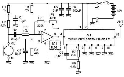
To relieve you of any concern related to high frequency, I used a module ready, in case a module Aurel audio FM transmitter. This tiny circuit board with 2 cm by 4 cm supports a transmitter modulation frequency track, delivering an RF power of 10 mW which is quite sufficient for the desired use. As it is driven by a resonator surface wave, its frequency stability is excellent.

As you can see the review of the scheme, the module can stand alone even for some HF itself since it lacks power and a network of pre-emphasis R7, R8, C6, designed to improve quality transmission of higher frequencies.

Schematic of the transmitter
Rangkaian Transmitter FM Wireless HI-FI

The input level required by the circuit to achieve a sufficient modulation rate of 100 mV rms, a preamplifier is necessary for our microphone. It is the role of IC1, mounted on a very classic inverting amplifier with adjustable gain through P1.

The provided microphone is a model electric with its supply circuit formed by R1, R2 and C1, but you might as well use a conventional dynamic mic, or an external electric microphone with its integrated power supply in which case R1, R2 and C1 disappear.

2. Receiver

As to the transmitter, I used a module Aurel, which is an FM audio receiver. It also appears as a tiny circuit board containing all the components of the receiver, equipped with a squelch circuit or quiet as I put to good use.

As illustrated, the audio output takes place on the leg 10 of the module and should be désaccentuée through capacitor C4 to offset the effect of pre-emphasis circuit used in the show. The AF level issued by the module may be insufficient for some high fidelity amplifiers or mixers certain: it is only 100 mV in the best cases I amplifies a bit through rose IC1 very classic.
Schematic of receiver

Rangkaian Receiver FM Wireless HI-FI

In order not to saturate the amplifier or mixer that follows, the adjustable potentiometer P1 can measure the level applied to it.

This preamplifier is fed continuously as the module Aurel but instead receives its power through the leg 18 of the latter. This output is in fact controlled by the internal circuit noise and is connected to power when the circuit noise estimates have detected a valid issue. The operating threshold of the muffler is adjustable and is obviously the role of the potentiometer P2 is the only external control of the receiver.

The food in turn must be regulated to 5 volts, which is made by IC2 which can receive input from 9 to 15 volts from such amplifier associated with a block or sector-style outlet . The low power consumption of the arrangement (of the order of 30 mA) makes this power supply.
read more "Control FM Wireless HI-FI Schematic"

Tuesday, August 7, 2012

Control Clap Switch

This clap switch can turn on and off a light,fan,music system,alarm.....virtually any gadget,at the sound of a clap.The most amazing part of the design is that it gives an a efficient two state control without employing any op amp,any counters,timers or flip-flops but just four transistor.The design shows how basic circuits can do complex jobs.

The sound is sensed by a small button microphone(condenser microphone)whose internal FET is biased by R1.The signal is amplified by T1,T2,T3,andT4 provides the remaining control functions.There isn't much to explain but much can be understood by carefully observing the design.T4 drivers a  relay.The relay is further used to control the load as shown in schematic b.It is the contacts of the relay that determine the loads that it can handle.
Schematic a
Schematic b

read more "Control Clap Switch"

Schematic GSM modem interfacing with microcontroller 8051 for SMS control of industrial equipments

GSM modem interfacing with microcontroller 8051 for SMS control of industrial equipments:-
This is a beginner tutorial in which a GSM modem is being interfaced with the microcontroller AT89s51 for SMS communication. The SMS can be send and recieved for the data sharing and situation information and control. there are many application of the project based on microcontroller 8051 and GSM interfacing. We can use it as a remote control of industrial machines or we can sue it for home automation or we can use it for the security of home or offices.
The sending SMS through GSM modem when interfaced with microcontroller or PC is much simpler as compared with sending SMS through Modem in PDU Mode.Text message may be sent through the modem by interfacing only three signals of the serial interface of modem with microcontroller i.e.,TxD,RxD and GND.In this scheme RTS and CTS signals of serial port interface of GSM Modem are connected with each other.The transmit signal of serial port of microcontroller is connected with transmit signal (TxD) of the serial interface of GSM Modem while receive signal of microcontroller serial port is connected with receive signal (RxD) of serial interface of GSM Modem.The COMPIM Serial Port Model shown in the schematic diagram developed in Proteus VSM is equivalent to the serial interafce of GSM Modem.Sending SMS Messages from a Computer / PC Using AT Commands (AT+CMGS, AT+CMSS)

block circuit diagram of GSM interface with microcontroller 8051
The following are the AT Commands and sequence of events performed for sending text message to a mobile phone through GSM Modem interfaced with microcontroller :


1. First select the text mode for SMS by sending the following AT Command to GSM Modem : AT+CMGF = 1 . This command configures the GSM modem in text mode.

2. Send the following AT Command for sending SMS message in text mode along with mobile number to the GSM Modem : AT+CMGS =+923005281046 . This command sends the mobile number of the recipient mobile to the GSM modem.

3. Send the text message string ("hello!") to the GSM Modem This is a test message from UART"
4. Send ASCII code for CTRL+Z i.e., 0x1A to GSM Modem to transmit the message to mobile phone.After message string has been sent to the modem, send CTRL+Z to the micro-controller,which is equivalent to 0x1A (ASCII value) Every AT command is followed by i.e. carriage return and line feed
you are giving line feed first and carriage return after that.
"\r" stands for carriage return

Interfacing 8051 with gsm modem equipped with RS232 serial interface is the same as interfacing AVR with GSM modem is.
The SMS message in text mode can contain only 140 characters at the most.It depends upon the amount of information collected from GPS Engine that you need at the base station for tracking vehicle or person
The most important string of GPS is "$GPRMC..." which contains the minimum information required in tracking a target additionally you may need the information regarding the number of satellites that are visible to the GPS receiver.So it depends upon how much information you need to pack in 140 characters of SMS in text mode.
code for the interfacing the GSM modem with microcontroller 8051 for just testing of connection and serial communication is under:-
#include // include at89x51 . h
#include // include stdio . h
#include // include stdlib . h
void initialize_GSM_modem(void);
void initialize_serialcommunication(void);
unsigned char Command_CMGF[]="AT+CMGF=1\r";
// AT+CMGF for selecting Text Mode
unsigned char CtrlZ=0x1A;                  
// CTRL+Z for sedning SMS after the message has been entered
unsigned char Command_CMGS[]="AT+CMGS =+9233385xxxxx\r";
// recepient mobile number
unsigned char Command_AT[]="AT\r";
unsigned char msg02[]="Hello!";
void delay(void){
unsigned int i;
for(i=0;i<50;i++);
}
 void delay2(void){
unsigned int i;
for(i=0;i<25000;i++);
}
void main (void) {
   initialize_GSM_modem();
 initialize_serialcommunication();
while (1) {
   ;
 }
 }   
 void initialize_GSM_modem(void){
 delay2();
puts(Command_AT);
delay2();
puts(Command_CMGF);
delay2();
puts(Command_CMGS);
delay2();
puts(msg02);
delay2();
while(!TI); TI = 0;SBUF = 0x1A;
 }
void initialize_serialcommunication(void){
TMOD = 0x20;
SCON = 0x50;       
TH1  = 0xFD;      
TL1  = 0xFD;       
TR1  = 1;
TI = 1;
}

Tags:-Introduction to SMS Messaging ,What Makes SMS Messaging So Successful Worldwide? , Example Applications of SMS Messaging , What is an SMS Center / SMSC? , Basic Concepts of SMS Technology , Intra-operator SMS Messages , Inter-operator SMS Messages , International SMS Messages , What is an SMS Gateway? , How to Send SMS Messages from a Computer / PC? , How to Receive SMS Messages Using a Computer / PC? , Introduction to GSM / GPRS Wireless Modems , How to Use Microsoft Hyper Terminal to Send AT Commands to a Mobile Phone or GSM/GPRS Modem? , Introduction to AT Commands , General Syntax of Extended AT Commands , Result Codes of AT Commands , AT Command Operations: Test, Set, Read and Execution , Testing the Communication between the PC and GSM/GPRS Modem or Mobile Phone ,Checking if the GSM/GPRS Modem or Mobile Phone Supports the Use of AT Commands to Send, Receive and Read SMS Messages , Operating Mode: SMS Text Mode and SMS PDU Mode , Setting or Reading the Service Center Address / SMSC Address (AT+CSCA) , Preferred Message Storage (AT+CPMS)
23. Writing SMS Messages to Memory / Message Storage (AT+CMGW) , Deleting SMS Messages from Message Storage (AT+CMGD) , Sending SMS Messages from a Computer / PC Using AT Commands (AT+CMGS, AT+CMSS) , Reading SMS Messages from a Message Storage Area Using AT Commands (AT+CMGR, AT+CMGL) SMS alarm je vrlo jednostavan uređaj. Za slanje SMS poruka koristi Siemens telefon a ima 5 ulaza - znači šalje 5 različitih poruka. Za svaki senzor uprogramiramo odgovarajuću poruku koju želimo da primimo na mobilni kada se alarm aktivira. Programiranje se vrši preko PC-a odgovarajućim programom koji je priložen u arhivi.
read more "Schematic GSM modem interfacing with microcontroller 8051 for SMS control of industrial equipments"

Monday, August 6, 2012

Control Versatile Intercom System

Most intercoms use up to five wires for hooking up to other units,while the one presented here needs just two.There are several features that make this design unique.

  • Two wire line systems.
  • Single chip design
  • Touch to call facility
  • Hands free conversation which allows conferencing
  • Compact design
The unit uses a type 1895 amplifier IC which forms the heart of  the unit.The amplifier takes the input from a biased microphone M1.The output is given to the line.Point A and E are connected to communication line.The basic design is conventional.When the touch plate is touched,a buzzing sound is sent to other unit to give the call signal.This is due to the ambient mains hum pickup and its harmonics.

The 8 ohm speakers is used if two units are used.For four,each speaker must be a 16 ohm type.The microphone is the usual tape recorder type.A suitable power supply is given in schematic b.
Schematic a :This intercom needs just two outgoing wires 
while most others would need at least five.

Schematic b :The power supply set up

The final wiring is done as shown in Picture As for enclosures,even cases will do the job well enough.
 Picture : Wiring Schematic for two units.


read more "Control Versatile Intercom System"

Control Solid State Tube Light Choke

The advantages of tube light over filament bulbs are well known.But these tube lights have problems too.They refuse to work at lower voltages,they are costly,burn out easily and so on.So,presented here is a unique solid state electronic design.

The circuit is shown in schematic a it uses two capacitors and four diodes and work along with a 100 watt bulb.The tube lights operated with this choke were found to work at voltage as low as 120 volts(in the 220 volt lines).The circuit provides a pulsating voltages to the fluorescent tube light fixed on a conventional stand.

read more "Control Solid State Tube Light Choke"

Control Toggling Touch Switch

With just one single IC and that also not a digital one ,as one would expect,this switch would from probably one of the austeriest ever made.

The circuit described here allows any electric or electronic devices to be remotely switched on and off just by touching the touch plates.This not only ensures higher safety,but also lends elegance and gives them a longer life.The circuit uses the internal flip-flop of the 555 timer.The two touch plates are used to switch on/off the relay,which controls the relay .Though a 9 volt relay has been recommended,voltages after replacing the relay can be varied from 6 to 12 volts.

The load that the circuit can support depends upon the rating of the relay contacts.The circuit can work on a simple unregulated power supply.The only care that needs to be taken is that the circuit must not be connected to touch plates using wires longer than three meters . The wires used for these connections must be shield in order to prevent false triggering.


read more "Control Toggling Touch Switch"

Thursday, August 2, 2012

Control Dual Channel 70V Voltmeter Using PIC


This is a circuit for dual channel voltmeter. This circuit is based on PIC microcontroller. This is the figure of the circuit;


PIC voltmeter can measure 0-70 Volts which should be more than enough for most of electronic projects providing excellent reading accuracy and resolution. It has two input channels for measuring two voltage sources at the same time. This PIC voltmeter project uses PIC16F876 microcontroller with built-in ADC (Analog to Digital Converter) and 2x16 back lighted LCD display.
read more "Control Dual Channel 70V Voltmeter Using PIC"