Monday, December 31, 2012

Control Variable DC Power Supply With LM317

This DC power supply circuit is adjustable using IC Voltage Regulator LM317. LM317 is a versatile and highly efficient 1.2-37V voltage regulatorthat can provide up to 1.5A of current with a large heat sink. It'sideal for just about any application. This was my first workbench powersupply and I still use it.

Since LM317 is protectedagainst short-circuit, no fuse is necessary. Thanks to automaticthermal shutdown, it will turn off if heating excessively. All in all,a very powerful (and affordable!) package, indeed.

Although voltage regulator LM317 is capable of delivering up to 37V, the DC power supplyoutput circuit here is limited to 25V for the sake of safety andsimplicity. Any higher output voltage would require additionalcomponents and a larger heat sink.

Make sure that theinput voltage is at least a couple of Volts higher than the desiredoutput. It's OK to use a trim-pot if you're building a fixed-voltagesupply.

Problems:
Follow all the safety precautions when working with mains voltage. Insulate all connections on the transformer.
read more "Control Variable DC Power Supply With LM317"

Friday, December 28, 2012

Control 6A, 5 Volt Power Supply

The standard variable voltage regulator type LM150 is fairly easily available, but at times its out, which is limited to about 3 amperes, may prove to e a limiting factor to its utility, nut the simple modification describe here allows the to be enhanced to about 6 amperes. The circuit has inbuilt safe area protection and thermal overload protection.The circuit has been tested for lone regulation of the order of about 0.01% volt and load regulation of about 0.1% volt.
The circuit works on principle similar to the compact 10A power supplies. The two LM150 regulators are wired in parallel mode with  IC3 which controls them. The output voltage is given by the relation
Vout=1,25x(1+R5/R4) volts. The input voltage may lie anywhere in the range of 12 to 30 volts.

The IC must be adequately heat sinked in order to obtain full output current all over the operative temperature range 

The circuit 6A, 5 volt Power Supply
read more "Control 6A, 5 Volt Power Supply"

Control 32W HiFi Amplifier circuit based on TDA2050

This is a High Fidelify (Hi-Fi) amplifier circuit based on single IC TDA205. This is a mono channel audio amplifier. You need to build the same circuit for stereo channel.


TDA2050 Description:
The TDA 2050 is a monolithic integrated circuitin Pentawatt package, intended for use as an audio class AB audioamplifier. Thanks to its high power capability the TDA2050 is able toprovide up to 35W true rms power into 4 ohm load @ THD =10%, VS = ±18V,f = 1KHz and up to 32W into 8ohm load @ THD = 10%, VS = ±22V, f = 1KHz.Moreover, the TDA 2050 delivers typically 50W music power into 4 ohmload over 1 sec at VS=22.5V, f = 1KHz.
The high power and verylow harmonic and crossover distortion (THD = 0.05% typ, @ VS = ±22V, PO= 0.1 to 15W, RL=8ohm, f = 100Hz to 15KHz) make the device mostsuitable for both HiFi and high class TV sets.
read more "Control 32W HiFi Amplifier circuit based on TDA2050"

Thursday, December 27, 2012

Control High Current Regulated Supply

The high current regulator below uses an additional winding or a separate transformer to supply power for the LM317 regulator so that the pass transistors can operate closer to saturation and improve efficiency. For good efficiency the voltage at the collectors of the two parallel 2N3055 pass transistors should be close to the output voltage. The LM317 requires a couple extra volts on the input side, plus the emitter/base drop of the 3055s, plus whatever is lost across the (0.1 ohm) equalizing resistors (1volt at 10 amps), so a separate transformer and rectifier/filter circuit is used that is a few volts higher than the output voltage. The LM317 will provide over 1 amp of current to drive the bases of the pass transistors and assumings a gain of 10 the combination should deliver 15 amps or more. The LM317 always operates with a voltage difference of 1.2 between the output terminal and adjustment terminal and requires a minimum load of 10mA, so a 75 ohm resistor was chosen which will draw (1.2/75 = 16mA). This same current flows through the emitter resistor of the 2N3904 which produces about a 1 volt drop across the 62 ohm resistor and 1.7 volts at the base. The output voltage is set with the voltage divider (1K/560) so that 1.7 volts is applied to the 3904 base when the output is 5 volts. For 13 volt operation, the 1K resistor could be adjusted to around 3.6K. The regulator has no output short circuit protection so the output probably should be fused.
read more "Control High Current Regulated Supply"

Control TDA7295, 80W Audio Amplifier

Below is a 80W amplifier circuit is constructed by using a power ICTDA7295. With a very simple design, makes this circuit very easy tobuild. TDA7295 has many features to support your audio system, the most important is that the IC has very low distortion and very low noise feature.


The TDA7295 is a monolithic integrated circuit in Multiwatt15package, intended for use as audio class AB amplifier in Hi-Fi fieldapplications such as home theatre and topclass TV. The wide voltagerange and to the high out current capability make the TDA7295 able tosupply the highest power into both 4W and 8W loads even in presence ofpoor supply regulation, with high Supply Voltage Rejection.
The built in muting function with turn on delay simplifies the remote operation avoiding switching on-off noises.
read more "Control TDA7295, 80W Audio Amplifier"

Wednesday, December 26, 2012

Control 10W Audio Amplifier circuit based on TDA1910

Simple and cheap, that's the advantage of this circuit. Although the output power is not high but audio quality is good, because TDA1910 has a very low noise feature. This circuit suitable for use as a student project.

About TDA1910:
The TDA1910 is a monolithic integrated circuit in MULTIWATT® package, intended for use in Hi-Fi audio power applications, as high quality TV sets.
TheTDA 1910 meets the DIN 45500 (d = 0.5%) guaranteed output power of 10Wwhen used at 24V/4W. At 24V/8W the output power is 7W min.
TDA1910 Features:
  • muting facility
  • protection against chip over temperature
  • very low noise
  • high supply voltage rejection
  • low “switch-on” noise.
read more "Control 10W Audio Amplifier circuit based on TDA1910"

Tuesday, December 25, 2012

Control Digital Remote Thermometer Circuit With Receiver and Transmitter

Remote sensor sends data via mains supply, Temperature range: 00.0 to 99.9 °C

This circuit is intended for precision centigrade temperature measurement, with a transmitter section converting to frequency the sensor's output voltage, which is proportional to the measured temperature. The output frequency bursts are conveyed into the mains supply cables. The receiver section counts the bursts coming from mains supply and shows the counting on three 7-segment LED displays. The least significant digit displays tenths of degree and then a 00.0 to 99.9 °C range is obtained. Transmitter-receiver distance can reach hundred meters, provided both units are connected to the mains supply within the control of the same light-meter.

Transmitter circuit operation:

IC1 is a precision centigrade temperature sensor with a linear output of 10mV/°C driving IC2, a voltage-frequency converter. At its output pin (3), an input of 10mV is converted to 100Hz frequency pulses. Thus, for example, a temperature of 20°C is converted by IC1 to 200mV and then by IC2 to 2KHz. Q1 is the driver of the power output transistor Q2, coupled to the mains supply by L1 and C7, C8.

Circuit diagram:

Transmitter parts:


R1 = 100K 1/4W Resistors
R2 = 47R 1/4W Resistor
R3 = 100K 1/4W Resistors
R4 = 5K 1/2W Trimmer Cermet
R5 = 12K 1/4W Resistor
R6 = 10K 1/4W Resistor
R7 = 6K8 1/4W Resistor
R8 = 1K 1/4W Resistors
R9 = 1K 1/4W Resistors

C1 = 220nF 63V Polyester Capacitor
C2 = 10nF 63V Polyester Capacitor
C3 = 1µF 63V Polyester Capacitor
C4 = 1nF 63V Polyester Capacitors
C5 = 2n2 63V Polyester Capacitor
C6 = 1nF 63V Polyester Capacitors
C7 = 47nF 400V Polyester Capacitors
C8 = 47nF 400V Polyester Capacitors
C9 = 1000µF 25V Electrolytic Capacitor

D1 = 1N4148 75V 150mA Diode
D2 = 1N4002 100V 1A Diodes
D3 = 1N4002 100V 1A Diodes
D4 = 5mm. Red LED

IC1 = LM35 Linear temperature sensor IC
IC2 = LM331 Voltage-frequency converter IC
IC3 = 78L06 6V 100mA Voltage regulator IC

Q1 = BC238 25V 100mA NPN Transistor
Q2 = BD139 80V 1.5A NPN Transistor
T1 = 220V Primary, 12+12V Secondary 3VA Mains transformer
PL = Male Mains plug & cable
L1 = Primary (Connected to Q2 Collector): 100 turns
Secondary: 10 turns
Wire diameter: O.2mm. enameled
Plastic former with ferrite core. Outer diameter: 4mm.

Receiver circuit operation:

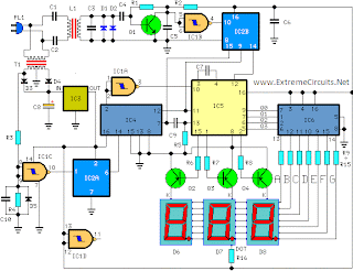
The frequency pulses coming from mains supply and safely insulated by C1, C2 & L1 are amplified by Q1; diodes D1 and D2 limiting peaks at its input. Pulses are filtered by C5, squared by IC1B, divided by 10 in IC2B and sent for the final count to the clock input of IC5. IC4 is the time-base generator: it provides reset pulses for IC1B and IC5 and enables latches and gate-time of IC5 at 1Hz frequency. It is driven by a 5Hz square wave obtained from 50Hz mains frequency picked-up from T1 secondary, squared by IC1C and divided by 10 in IC2A. IC5 drives the displays' cathodes via Q2, Q3 & Q4 at a multiplexing rate frequency fixed by C7. It drives also the 3 displays' paralleled anodes via the BCD-to-7 segment decoder IC6. Summing up, input pulses from mains supply at, say, 2KHz frequency, are divided by 10 and displayed as 20.0°C.

Circuit diagram:
Receiver Circuit Diagram
Receiver Parts:

R1 = 100K 1/4W Resistor
R2 = 1K 1/4W Resistor
R3 = 12K 1/4W Resistors
R4 = 12K 1/4W Resistors
R5 = 47K 1/4W Resistor
R6 = 12K 1/4W Resistors
R8 = 12K 1/4W Resistors
R9-R15=470R 1/4W Resistors
R16 = 680R 1/4W Resistor

C1 = 47nF 400V Polyester Capacitors
C2 = 47nF 400V Polyester Capacitors
C3 = 1nF 63V Polyester Capacitors
C4 = 10nF 63V Polyester Capacitor
C7 = 1nF 63V Polyester Capacitors
C5 = 220nF 63V Polyester Capacitors
C6 = 220nF 63V Polyester Capacitors
C8 = 1000µF 25V Electrolytic Capacitor
C9 = 100pF 63V Ceramic Capacitor
C10 = 220nF 63V Polyester Capacitors

D1 = 1N4148 75V 150mA Diodes
D2 = 1N4148 75V 150mA Diodes
D3 = 1N4002 100V 1A Diodes
D4 = 1N4002 100V 1A Diodes
D5 = 1N4148 75V 150mA Diodes
D6 = Common-cathode 7-segment LED mini-displays
D7 = Common-cathode 7-segment LED mini-displays
D8 = Common-cathode 7-segment LED mini-displays

IC1 = 4093 Quad 2 input Schmitt NAND Gate IC
IC2 = 4518 Dual BCD Up-Counter IC
IC3 = 78L12 12V 100mA Voltage regulator IC
IC4 = 4017 Decade Counter with 10 decoded outputs IC
IC5 = 4553 Three-digit BCD Counter IC
IC6 = 4511 BCD-to-7-Segment Latch/Decoder/Driver IC

Q1 = BC239C 25V 100mA NPN Transistor
Q2 = BC327 45V 800mA PNP Transistors
Q3 = BC327 45V 800mA PNP Transistors
Q4 = BC327 45V 800mA PNP Transistors

PL = Male Mains plug & cable
T1 = 220V Primary, 12+12V Secondary 3VA Mains transformer
L1 = Primary (Connected to C1 & C2): 10 turns
Secondary: 100 turns
Wire diameter: O.2mm. enameled
Plastic former with ferrite core. Outer diameter: 4mm.

Notes:
  • D6 is the Most Significant Digit and D8 is the Least Significant Digit.
  • R16 is connected to the Dot anode of D7 to illuminate permanently the decimal point.
  • Set the ferrite cores of both inductors for maximum output (best measured with an oscilloscope, but not critical).
  • Set trimmer R4 in the transmitter to obtain a frequency of 5KHz at pin 3 of IC2 with an input of 0.5Vcc at pin 7 (a digital frequency meter is required).
  • More simple setup: place a thermometer close to IC1 sensor, then set R4 to obtain the same reading of the thermometer in the receiver's display.
  • Keep the sensor (IC1) well away from heating sources (e.g. Mains Transformer T1).
  • Linearity is very good.
  • Warning! Both circuits are connected to 230Vac mains, then some parts in the circuit boards are subjected to lethal potential! Avoid touching the circuits when plugged and enclose them in plastic boxes.
From Extremecircuit.net
read more "Control Digital Remote Thermometer Circuit With Receiver and Transmitter"

Sunday, December 23, 2012

Control Line follower with atmega 16

Here the complete electrical circuit diagram of line follower robot which built based on ATmega16. There are three modules of line follower robot circuit that are sensor module, microcontroller module and DC motor module.
IR sensor schematic diagram:
ir sensor circuit diagram
Mainboard (microcontroller + DC motor driver schematic diagram):
atmega16 circuit diagram
read more "Control Line follower with atmega 16"

Friday, December 21, 2012

Control Power LED Flasher

The low cost and extremely compact circuit given here is that of a highly power saving flashing LED indicator.Whereas most LEDs fail to work below 2 volt, their forward voltage alone being 1,6 volts minimum, this flasher can work off one single cell.

The LM3909 contains virtually all the essential trigger and pulsing circuitry which controls the flashing rate. The only other component used is the capacitor C1 which decides the final flashing rate, which in this case is set to about 1Hz.

The circuit has very low current has a very low current consumption, in the order of about 0.3mA, which is made possible due to intermittent current flow in the form of very short pulse through the LED. The capacitor connected across the cell ensures that the circuit continues to operate even when voltage falls below 1.2 volt (minimum limit).

The  circuit, if assembled closely on a veroboard, would occupy little extra space as compared to a conventional neon or LED indicator.

  The Schematic Power LED Flasher
read more "Control Power LED Flasher"

Wednesday, December 19, 2012

Control NiCad Batteries Charger

This battery charger circuit is designed for recharging Ni Cad batteries based on an AC-powered current source method. It can crank out as much as 1 amp and can be modified to go even higher by choosing different devices for Q1. Since this circuit uses AC line voltages and currents, please exercise extreme caution during assembly, turn-on, and test.

NiCAD batteries have a capacity specification called milliamp-hours. This value called "C" is a measure of how much total current they can provide in one hour. Milliamp-hours is another way to express the energy contained in the battery. To recharge a Ni CAD battery conservatively, it is common practice to pump a current of 0.1 C into the anode or positive terminal for about 12 hours. Therefore, if you had a D-size NiCAD with a capacity of 4000mAh, you would want to charge it at 400mA for about 12 hours. Another advantage of this charging technique is that it is gentle on batteries and doesn't cause them to lose capacity as quickly as the fast charge techniques.

The output current of this battery charger circuit is controlled by the summation of the bandgap reference diode and the base-emitter junction of the PNP transistor. The PNP transistor provides negative feedback to the gate of the MOSFET. As noted in the schematic, the batteries being charged can have a total of 12V which is equivalent to about 8 NiCAD's in series. The output current is determined by the value of R1 which is determined by:

R1=3.2Volts/Iout

The power dissipation of R1 will equal:

Pr1=3.2Volts*Iout

Be sure to provide plenty of heat sink for Q1 and choose an appropriately sized resistor for R1. The following table summarizes some of the resistor current combination that are possible:
Iout Resistor Value Resistor Power
100mA 33 ohms 1 watt
500mA 6.2 ohms 2 watt
1Amp 3.3 ohms 5 watt
read more "Control NiCad Batteries Charger"

Tuesday, December 11, 2012

Control Perkembangan semikonduktor

Semikondutor adalah bahan yang paling banyak digunakan pada peralatan elektronika sekarang ini.Sifatnya yang khusus membuat semikonduktor sangat khas dalam tingkat atom. Semikonduktro adalah bahan yang mempunyai sifat antara konduktor dan isolasi. Pada saat tertentu semikondukto bisa menjadi isolasi maupun konduktor hal ini biasanya diakibatkan oleh pengaruh dari luar misalnya panas.

Pada abad ke 20 ini penemuan semikonduktor telah membawa manusia ke jaman paling modren yang tidak pernah terbayangkan oleh manusia dulunya. Saat ini semua alat yang dipakai oleh manusia tidak lepas dari semikonduktor. Aplikasinya banyak kita lihat pada peralatan elektronika. Dengan penemuan semikonduktor telah peralatan yang dulunya rumit (dengan cara analog) menjadi sangat sederhana. Misalnya pemakain IC,Serta mikroprosesor
read more "Control Perkembangan semikonduktor"

Thursday, December 6, 2012

Control Dasar Digital dan Mikroprosesor (UNIT ARITMATIKA & FLIP-FLOP)

Gambar  ini adalah gambar awal mulanya  Mikroprosesor dibuat namanya adalah SAP1( Simple As Possible ) Tujuannya adalah untuk menunjukan gagasan penting operasi komputer

Pencacah Program PC mencacah dari 0000 sampai 1111 dengan hexsadesimal 0 sampai F.

RegisterAlamat Memori (MAR)
MAR menerima alamat  biner dari pencacah program

Akumulator
yakni sekelompok flip-flop yang menyimpan jawaban sementara pada kerja komputer

Satuan Arimatika -Logikal (ALU)
Mengandung penambahan dan pengurangan  pelengkap 2

Sistem diatas terintegrasi menjadi satu yang datanya nantinya akan berpindah melalui BUS dimana satu sama lain akan terkoneksi. Konsep komputer diatas menjadi cikal bakal dari perkembangan komputer sekarang jadi untuk meningkatkan kinerja komputer banyak faktor yang akan mempengaruhi.
read more "Control Dasar Digital dan Mikroprosesor (UNIT ARITMATIKA & FLIP-FLOP)"

Control TEA6320 Multichannel Audio Selector and Volume Control Circuit

This is a design circuit for high-end audio equipments are normally digitally controlled by a microprocessor (microcontroller) system. It’s necessary to have  digital interface that provide control for audio signal switching, as well as programming the gain to control the signal volume. This is the figure of the circuit;
 

TEA6320 comes with the solution for digital control of audio source channel selector and volume control, very useful integrated circuit for modern audio or stereo application with embedded digital control. For more information on how to use this audio signal control IC chip, see the datasheet.

read more "Control TEA6320 Multichannel Audio Selector and Volume Control Circuit"

Saturday, November 24, 2012

Control Line Follower ROBOT Controlled by 2051

This Robot use two motors control  rear wheels and the single front wheel is free. It has 4-infrared sensors on the bottom for detect black tracking tape, when the sensors detected black color, output of  comparator, LM324 is low logic and the other the output is high.
Microcontrollor AT89C2051 and H-Bridge driver L293D were used  to control direction and speed of motor.

Fig 1. Circuit diagram of my Robot.

 Fig 2. Circuit diagram of Infrared sensors and comparators.


read more "Control Line Follower ROBOT Controlled by 2051"

Friday, November 23, 2012

Control AC to DC 90 Watt Switching Power Adaptor

AC to DC switching power adaptor circuit with maximum output power of 90W. Switching power supply is built using a high voltage power switching regulator IC MC33374 and some other additional components. The MC33374 IC is a monolithic high voltage power switching regulators that are specially designed to operate directly from a rectified AC line source, and in flyback converter applications.
The MC33374 switching power adaptor combines the required converter functions with a unique programmable state controller. At various variable AC inputs, it is capable of serving up to 6 A current at 15V output voltage. This switching power adaptor is capable of providing an output power in excess of 150W with a fixed AC input of 100V, 115V, or 230V, and in excess of 90 W with a variable AC input that ranges from 85V to 265V.

Circuit AC to DC 90 Watt Switching Power Adaptor
read more "Control AC to DC 90 Watt Switching Power Adaptor"

Thursday, November 22, 2012

Control Basic Phototransistor Detector

This is a Phototransistor Detector circuit. In this circuit, when the light falling on the phototransistor (Q1) is blocked, its conductance will decrease and the voltage across Q1 will rise. When the voltage rises above 1/2 of the supply voltage the output of the comparator will turn ON and the LED will be lit.

The only critical part of this circuit is the value of resistor R1 which in most cases can be 470K ohms but may have to be increase if the room is dark or decreased if the room is well lit.
Increasing the value of R1 will cause the sensitivity of the sensor to decrease. This may be necessary when the light falling on the cell is not very strong or shadows can affect the phototransistor.
There are a number of phototransistors sizes and case styles. The smaller cases will be easier to hide but connecting wires may be more difficult.
read more "Control Basic Phototransistor Detector"

Monday, November 12, 2012

Control Mobile Phone Charger Circuit For Traveling

Here is an ideal Mobile charger using 1.5 volt pen cells to charge mobile phone while traveling. It can replenish cell phone battery three or four times in places where AC power is not available. Most of the Mobile phone batteries are rated at 3.6 V/500 mA. A single pen torch cell can provide 1.5 volts and 1.5 Amps current. So if four pen cells are connected serially, it will form a battery pack with 6 volt and 1.5 Amps current. When power is applied to the circuit through S1, transistor Q1 conducts and Green LED lights.

When Q1 conducts Q2 also conducts since its base becomes negative. Charging current flows from the collector of Q1. To reduce the charging voltage to 4.7 volts, Zener diode D2 is used. The output gives 20 mA current for slow charging. If more current is required for fast charging, reduce the value of R4 to 47 ohms so that 80 mA current will be available. Output points are used to connect the charger with the mobile phone. Use suitable pins for this and connect with correct polarity. The circuit comes from here.

The Schematic Mobile Phone Charger Circuit For Traveling

Parts:

R1 = 1K
R2 = 470R
R3 = 4.7K
R4 = 270R
R5 = 27R
C1 = 100uF-25V
D1 = Green LED
D2 = 4.7V/1W Zener
B1 = 1.5Vx4 Cells
S1 = On/Off Switch
Q1 = BC548
Q2 = SK100
read more "Control Mobile Phone Charger Circuit For Traveling"

Thursday, November 8, 2012

Control Printing Compact for Windows Mobile

Today, in turn for the net, I have found a notice interesting. Polaroid, in co
llaboration with Zink Imaging has intention to release to short (the precise date still has not been specified) a new printing for photo super capacities them. The new “Digital Mobile Instant Photo Printer” will be equipped of Bluetooth logo's, in order to allow to print photo from the cellular one and Pocket PC without having to connect some cable, and Pict Bridge USB, compatible with the majority of blots some photographic in commerce. One of the characteristics that they hit more is technology ZINK (Zero Ink Printing Technology) used for the press process. This technology in fact I use not to preview it of cartridges, but the photos come printed publication on a special paper through the stimulation of the present polymers on this last one. The declared dimensions are 120x72x23 millimeter with a weight of 230 grams approximately (Enclosed batteries).
read more "Control Printing Compact for Windows Mobile"

Tuesday, November 6, 2012

Control Windows seven WP7 Tips and Tricks - To associate a Bluetooth device


The appointment today with the Guides and Trucchi for
Windows Phone 7 is dedicated to the Bluetooth, and in particular to like
associating a cap, an earpiece, an external keyboard or any Bluetooth accessory
to I telephone Windows Phone 7. First of all we must ignite the Bluetooth.


* From the shielded Start we slide to sinistra per visualizing the
directory of the Applications.


*We slide the list and we touch on the Impostazioni.


* We touch the Bluetooth voice and we change the State on Ignited


* In this Windows moment it is already trying the present Bluetooth devices
near I telephone. We make sure therefore that our accessory already is ignited.


* Al term of the search we will see a directory with the several names of the
found accessories. We touch therefore what we want to install.


* To this point it could be demanded a PIN in order to associate the two
devices. Inserted therefore the present code in the handbook of the accessory
or a new one and touched on

read more "Control Windows seven WP7 Tips and Tricks - To associate a Bluetooth device"

Monday, November 5, 2012

Control Digital Remote Thermometer Circuit With Receiver and Transmitter

Remote sensor sends data via mains supply, Temperature range: 00.0 to 99.9 °C

This circuit is intended for precision centigrade temperature measurement, with a transmitter section converting to frequency the sensor's output voltage, which is proportional to the measured temperature. The output frequency bursts are conveyed into the mains supply cables. The receiver section counts the bursts coming from mains supply and shows the counting on three 7-segment LED displays. The least significant digit displays tenths of degree and then a 00.0 to 99.9 °C range is obtained. Transmitter-receiver distance can reach hundred meters, provided both units are connected to the mains supply within the control of the same light-meter.

Transmitter circuit operation:

IC1 is a precision centigrade temperature sensor with a linear output of 10mV/°C driving IC2, a voltage-frequency converter. At its output pin (3), an input of 10mV is converted to 100Hz frequency pulses. Thus, for example, a temperature of 20°C is converted by IC1 to 200mV and then by IC2 to 2KHz. Q1 is the driver of the power output transistor Q2, coupled to the mains supply by L1 and C7, C8.

Circuit diagram:

Transmitter parts:


R1 = 100K 1/4W Resistors
R2 = 47R 1/4W Resistor
R3 = 100K 1/4W Resistors
R4 = 5K 1/2W Trimmer Cermet
R5 = 12K 1/4W Resistor
R6 = 10K 1/4W Resistor
R7 = 6K8 1/4W Resistor
R8 = 1K 1/4W Resistors
R9 = 1K 1/4W Resistors

C1 = 220nF 63V Polyester Capacitor
C2 = 10nF 63V Polyester Capacitor
C3 = 1µF 63V Polyester Capacitor
C4 = 1nF 63V Polyester Capacitors
C5 = 2n2 63V Polyester Capacitor
C6 = 1nF 63V Polyester Capacitors
C7 = 47nF 400V Polyester Capacitors
C8 = 47nF 400V Polyester Capacitors
C9 = 1000µF 25V Electrolytic Capacitor

D1 = 1N4148 75V 150mA Diode
D2 = 1N4002 100V 1A Diodes
D3 = 1N4002 100V 1A Diodes
D4 = 5mm. Red LED

IC1 = LM35 Linear temperature sensor IC
IC2 = LM331 Voltage-frequency converter IC
IC3 = 78L06 6V 100mA Voltage regulator IC

Q1 = BC238 25V 100mA NPN Transistor
Q2 = BD139 80V 1.5A NPN Transistor
T1 = 220V Primary, 12+12V Secondary 3VA Mains transformer
PL = Male Mains plug & cable
L1 = Primary (Connected to Q2 Collector): 100 turns
Secondary: 10 turns
Wire diameter: O.2mm. enameled
Plastic former with ferrite core. Outer diameter: 4mm.

Receiver circuit operation:

The frequency pulses coming from mains supply and safely insulated by C1, C2 & L1 are amplified by Q1; diodes D1 and D2 limiting peaks at its input. Pulses are filtered by C5, squared by IC1B, divided by 10 in IC2B and sent for the final count to the clock input of IC5. IC4 is the time-base generator: it provides reset pulses for IC1B and IC5 and enables latches and gate-time of IC5 at 1Hz frequency. It is driven by a 5Hz square wave obtained from 50Hz mains frequency picked-up from T1 secondary, squared by IC1C and divided by 10 in IC2A. IC5 drives the displays' cathodes via Q2, Q3 & Q4 at a multiplexing rate frequency fixed by C7. It drives also the 3 displays' paralleled anodes via the BCD-to-7 segment decoder IC6. Summing up, input pulses from mains supply at, say, 2KHz frequency, are divided by 10 and displayed as 20.0°C.

Circuit diagram:
Receiver Circuit Diagram
Receiver Parts:

R1 = 100K 1/4W Resistor
R2 = 1K 1/4W Resistor
R3 = 12K 1/4W Resistors
R4 = 12K 1/4W Resistors
R5 = 47K 1/4W Resistor
R6 = 12K 1/4W Resistors
R8 = 12K 1/4W Resistors
R9-R15=470R 1/4W Resistors
R16 = 680R 1/4W Resistor

C1 = 47nF 400V Polyester Capacitors
C2 = 47nF 400V Polyester Capacitors
C3 = 1nF 63V Polyester Capacitors
C4 = 10nF 63V Polyester Capacitor
C7 = 1nF 63V Polyester Capacitors
C5 = 220nF 63V Polyester Capacitors
C6 = 220nF 63V Polyester Capacitors
C8 = 1000µF 25V Electrolytic Capacitor
C9 = 100pF 63V Ceramic Capacitor
C10 = 220nF 63V Polyester Capacitors

D1 = 1N4148 75V 150mA Diodes
D2 = 1N4148 75V 150mA Diodes
D3 = 1N4002 100V 1A Diodes
D4 = 1N4002 100V 1A Diodes
D5 = 1N4148 75V 150mA Diodes
D6 = Common-cathode 7-segment LED mini-displays
D7 = Common-cathode 7-segment LED mini-displays
D8 = Common-cathode 7-segment LED mini-displays

IC1 = 4093 Quad 2 input Schmitt NAND Gate IC
IC2 = 4518 Dual BCD Up-Counter IC
IC3 = 78L12 12V 100mA Voltage regulator IC
IC4 = 4017 Decade Counter with 10 decoded outputs IC
IC5 = 4553 Three-digit BCD Counter IC
IC6 = 4511 BCD-to-7-Segment Latch/Decoder/Driver IC

Q1 = BC239C 25V 100mA NPN Transistor
Q2 = BC327 45V 800mA PNP Transistors
Q3 = BC327 45V 800mA PNP Transistors
Q4 = BC327 45V 800mA PNP Transistors

PL = Male Mains plug & cable
T1 = 220V Primary, 12+12V Secondary 3VA Mains transformer
L1 = Primary (Connected to C1 & C2): 10 turns
Secondary: 100 turns
Wire diameter: O.2mm. enameled
Plastic former with ferrite core. Outer diameter: 4mm.

Notes:
  • D6 is the Most Significant Digit and D8 is the Least Significant Digit.
  • R16 is connected to the Dot anode of D7 to illuminate permanently the decimal point.
  • Set the ferrite cores of both inductors for maximum output (best measured with an oscilloscope, but not critical).
  • Set trimmer R4 in the transmitter to obtain a frequency of 5KHz at pin 3 of IC2 with an input of 0.5Vcc at pin 7 (a digital frequency meter is required).
  • More simple setup: place a thermometer close to IC1 sensor, then set R4 to obtain the same reading of the thermometer in the receiver's display.
  • Keep the sensor (IC1) well away from heating sources (e.g. Mains Transformer T1).
  • Linearity is very good.
  • Warning! Both circuits are connected to 230Vac mains, then some parts in the circuit boards are subjected to lethal potential! Avoid touching the circuits when plugged and enclose them in plastic boxes.
From Extremecircuit.net
read more "Control Digital Remote Thermometer Circuit With Receiver and Transmitter"

Control Mobile Phone Charger Circuit For Traveling

Here is an ideal Mobile charger using 1.5 volt pen cells to charge mobile phone while traveling. It can replenish cell phone battery three or four times in places where AC power is not available. Most of the Mobile phone batteries are rated at 3.6 V/500 mA. A single pen torch cell can provide 1.5 volts and 1.5 Amps current. So if four pen cells are connected serially, it will form a battery pack with 6 volt and 1.5 Amps current. When power is applied to the circuit through S1, transistor Q1 conducts and Green LED lights.

When Q1 conducts Q2 also conducts since its base becomes negative. Charging current flows from the collector of Q1. To reduce the charging voltage to 4.7 volts, Zener diode D2 is used. The output gives 20 mA current for slow charging. If more current is required for fast charging, reduce the value of R4 to 47 ohms so that 80 mA current will be available. Output points are used to connect the charger with the mobile phone. Use suitable pins for this and connect with correct polarity. The circuit comes from here.

The Schematic Mobile Phone Charger Circuit For Traveling

Parts:

R1 = 1K
R2 = 470R
R3 = 4.7K
R4 = 270R
R5 = 27R
C1 = 100uF-25V
D1 = Green LED
D2 = 4.7V/1W Zener
B1 = 1.5Vx4 Cells
S1 = On/Off Switch
Q1 = BC548
Q2 = SK100
read more "Control Mobile Phone Charger Circuit For Traveling"

Saturday, November 3, 2012

Control Motorola CommandOne, an earpiece bluetooth in order to write the SMS

To write SMS while guide is it self most dangerous. In some Countries he is also illegal and in passed they have been also of the serious incidents much for distractions of this type. The keyboards touchscreen, much fashionable ones in the smartphone more recent, than certainly of it do not facilitate the writing. Therefore Motorola it has created the earpiece bluetooth Command One.

Thanks to an application available for Android 2,2 and to the MotoSpeak technology, the customer can dictate the SMS to write and to send it without to watch the screen, simply dictating the commandos you premail. From the point of view hardware the earpiece is large 54 x 18,5 x 11 milimeter and hung 12 grams. The battery allows to an autonomy of 5 hours in conversation or 7 days in standby. In 15 minuteren, moreover, the battery is recharged of 50%. The device available for Will have been born them. Price not communicated.
read more "Control Motorola CommandOne, an earpiece bluetooth in order to write the SMS"

Friday, November 2, 2012

Control Simple Car Theft Deterrent

The purpose of this simple circuit is to deter potential car burglars by flashing a few LEDs on a seemingly very sophisticated control panel,implying that the vehicle is equipped with a sophisticated hi-tech alarm system. This simple deterrent is unique in the sense that it is based on just one single uni junction (UJT) and is connected to the car power supply system by just two wires.

The circuit partly relies on it self and partly on the psychological fact that on seeing a brightly lit and active control panel ( even when the car is off ) similar to an alarm system, many thieves, especially the more experienced ones, would don't like to.... to dare to attempt stealing the car at the risk of setting off the alarm.

The circuit as shown in schematic, is based on a UJT type 2N2646, which is wired as a low frequency oscillator. The frequency is determined by the timing  components R1 and C1. Two LEDs are used in flashing mode and two in normal forward conduction pilot mode.R2 and R3 limit the currents passing through the LEDs .       

The circuit Simple Car Theft Deterrent
read more "Control Simple Car Theft Deterrent"

Control Headlights On Indicator

Most drivers would have experienced the frustrations at some time or another of parking their car for the day and coming back in the evening only to find that they have accidentally left the head lights on. The result,with the modem small car batteries, quite often is that they have discharged the battery too much to start the engine. And at the end of a long day, the last thing one wants to cope with is a flat and discharged battery.

The basic objective of this low cost monitor is to prevent such (mis) happening from taking place. The circuit sounds an audible alarm as well as flashes a bicolour LED display array at the moment the driver,leaving the headlight on,open his door to leave the car. The alarm does not irritatingly sound every time a co-passenger opens a door. The circuit uses a single CMOS quad NAND gate chip,the ubiquitous 4093.

G1 is wired as a low frequency oscillator which flashes at around 1 Hz. For generating the AC current two 820 ohm resistors have been used rather than the conventional gate.G2 is wired as an AFO which generates the master alarm tone. G3 and G4 are used as buffers which drive the piezo element through the coupling capacitor C3.This piezo speaker has been used in place of normally used buzzers due to its advantages of lower height,lower cost as well as lower current demand.

     
The circuit of headlights on indicator

Diodes D1 and D2 ensure proper operation of the circuit by allowing the alarm to be actived only when the drivers door is opened.The circuit draws negligible current in quienscent state.
read more "Control Headlights On Indicator"

Thursday, November 1, 2012

Control The Pocket Receiver

Not that there is any paucity of pocket receivers or that they are too expensive,or that there are hardly any well known circuit that we decided to design' another one'. It's not just another one.

The True Pocket Receiver
 No doubt, dozens of models are commercially available but they aren't truly pocket sized (rather pocket oversized ). Not  many,leave alone the corner of a shirt pocket, fit into a normal shirt pocket leaving enough space to even tack a wallet, Well that's the reason we thought of designing a pocket receiver small enough to fit into a shirt pocket or clip on to a belt that is - a pocket receiver in the true sense. And that exactly is what we have here !


How it Works?
 The circuit is given in picture.It uses an 8-pin DIP ZN415 radio receiver chip from Ferranti. The circuit has an edge over the ZN414 in having an in-built amplifier stage. The IC contains a complete AM detector subsystem. The circuit uses a tuned circuit based on L1 and VC1 serves as tuning control.L1 detects the signals and passe them on to IC1, which in turn, drives high impedance headphones. That's all.

The IC thus allows construction of a light weight,low voltage and quality receiver.


read more "Control The Pocket Receiver"

Thursday, October 18, 2012

Control 3A Universal Power Supply

This universal power supply is universal in the true sense. With a output continually variable from 1.25 volts to 25 volts, this power supply is left with hardly any needs that it can't fulfill.The power supply is short circuit protected and  has in-built thermal overload protection.

As shown in figure, the power supply uses an LM350 type variable regulator. The IC in a TO-3 package and resembles the common 2N3055 and AD149 transistors. VR1 provides voltage control.R1,D2 and C2 are the accompanying components. The input voltage is obtained from an 30 volt source such as a transformer etc. The diode D1 provides a path for C3 to discharge  when the power is turned off. The output wires carry heavy currents, so adequate care must be taken to ensures the use of thick wires and terminal to prevent failures.A standard transistors type heat-sink must be used. 
read more "Control 3A Universal Power Supply"

Wednesday, October 17, 2012

Control DC motor control a AVR ATmega8

DC motor control using the PWM counters of AVR ATmega8 microcontroller. I had used a DC motor from an old personal stereo cassette player. The circuit provides speed and direction control of the motor. The PWM waveforms are used for driving the MOSFET H-bridge as shown in the schematic:

At a time only one of the two PWM channel is active, driving only two MOSFETS (either Q1-Q4 or Q3-Q2). Other two MOSFETs remain OFF. Whenever the Direction Control switch is toggled, the PWM channel is also changed, driving the alternative pair of MOSFET, which changes the direction of current flow through motor, resulting in the direction change in rotation of motor shaft.
read more "Control DC motor control a AVR ATmega8"

Saturday, October 13, 2012

Control Iran Introduces Walking Humanoid Soorena Robot

Iranian President Mahmoud Ahmadinejad unveiled a new Asimo-likerobot, which they intend to use in “sensitive jobs,” according togovernment newspapers. The report did not elaborate what the robot cando apart from dragging its feet across the floor.
Soorena-2, which was named after an ancient Persian warrior,measures 1.45 meters (4 feet 9 inches) in height and weighs 45kilograms (almost 100 pounds). It was an updated creation by therobotics team at Tehran University after its predecessor was introducedtwo years ago.
Another news reports that the Soorena-2 will eventually get visionand speech modules. The robot is part of a number of scientificprojects Iran has been researching, from cloning to stem cell researchto satellite technology.

A new Iranian humanoid robot called Soorena-2 has been designedby developed by 20 researchers and engineers from the University ofTehran to be used to conduct what are being called "sensitive jobs".What these jobs actually are we don’t know. The President MahmoudAhmadinejad just recently showed off this 4.7-foot walking robot to theworld. Soorena’s, who’s been named after an ancient Persian warrior,weighs in at 99 pounds and is capable of 12 foot movements, eight handmovement and the two for the head. We still don’t know exactly whatSoorena-2 is capable of, or is just one of those technologicaladvancements one likes to show off.

read more "Control Iran Introduces Walking Humanoid Soorena Robot"

Tuesday, October 9, 2012

Control BlackBerry VM-605 Specification

The BlackBerry VM-605 features a loud speaker for clear calls. Built-in FM transmission allows drivers to make use of their vehicle’s stereo for calls and music. The most interesting features in the VM-605 is that it was designed to work with GPS applications like TeleNav that announce your directions over the speakerphone. BlackBerry has included a button lock function. Holding the FM, Volume Up, and Front Panel buttons for four seconds will power off the unit and lock the keys, preventing accidental calls. Repeat the process to awaken the unit.

More Specifications Blackberry VM-605 :
* Music and calls through your car stereo speakers: Play calls and music from your cell phone on your car stereo via FM and Bluetooth transmission. FM Transmission with Auto Station Scanning for a surround sound effect.
* Multiple Languages: Easy to operate because the VM-605 gives spoken information in 9 languages. Blackberry VM-605 also speaks the CALLER ID so you control who to answer!
* Echo and Noise Cancellation: Background noise reduction and echo cancellation makes calls clear.
* GPS Application: VM-605 Speakerphone is designed to work with GPS applications like TeleNav that annouce your directions over the speakerphone or car stereo. * Compatible with select third-party GPS mapping applications. Check with your service provider for supported features and services.
* Battery: Talk continuously for up to 13 hours OR standby for up to 240 hours before you need to recharge the internal 1100mAh Lithim Polymer battery. Automatic Time-Out shutdown feature also saves battery life. Recharge from the included Micro USB auto charger or any other AC or DC Micro USB Charger.
* Lightweight and compact: Blackberry VM-605 weighs 86 grams (3.03 oz.), and measures only 123 mm x 57.6 mm x 16 mm (4.84 inches x 2.27 inches x 0.63 inches).
* Automatic reconnect: Auto-pairing for no-nonsense start up with your cell phone.
* Basic call handling: Features Answer/end calls, Reject calls, Voice-dialing through your cell phone, Last number redialing, and Mute.
* Bluetooth A2DP, HF and HSP profiles are all supported on this Bluetooth version 2.0, class 2 device for better connectivity up to 30 feet away
* Click here to determine if your cell phone model is Bluetooth enabled, AND which Bluetooth profiles it can support.
* RIM Blackberry factory original one year warranty applies.
* Price range:  $59.99 – $74.99
read more "Control BlackBerry VM-605 Specification"

Tuesday, October 2, 2012

Control RAM and ROM memories in Micoprosesor

Computer memory devices come in two basic types,RAM and ROM. these words are not as helpful as they could be.RAM standers for 'random access memory, a term which can in fact be applied to both types.ROM is 'read only memory'  which means that the computer system can obtain information stored in the memory('read' it) but can't store anything new in it('write' to it').RAM stores can boat be read from and written to,but both ROM and RAM have the random access facility.Put simply,this means that any data byte stored in the memory chip can be obtained as easily as the next, it doesn't matter whereabouts in the chip it is.

floppy disc systems offer the same facility A program stored anywhere on the disc can (to all intents and purpose) be just quickly accessed as any other.Compare this to information stored on magnetic tape.The first program on the tape is much easier to access than the last -  if you want to do it automatically- so that a tape memory is not regard as being random access.

Rom memory chips are programmed by the manufacture; they contain the computer operating system and standard routines (mini program) that may be used quite frequently;there may be a routine to clear the screen,for example.This information is stored permanently in the ROM chip and is not lost when power to the machine is switched  off. It is termed a 'non-volatile' memory.There is no possibility at all of making future changes to the contents of a ROM chip.The ROM, as with all semiconductor memory devices,is in matrix form and the connections within are permanent.

RAM chips are used for storing the user's program,you can write information the them and read it back again entirely at random according to your programming needs,but all the information's is lost when the computer system is switched off; this is therefore termed a 'volatile' memory system.

 A user would normally 'save' the contents of RAM (usually the program) on floppy or hard disc before turning the power off; such systems are called memory backing store. It is possible to write a program and have is stored  permanently in a ROM chip, but the process is quite complex and requires programmable ROM is used which is programmed during manufacture and would be too expensive to produce in small quantities.


read more "Control RAM and ROM memories in Micoprosesor"

Tuesday, September 25, 2012

Control The silicon chips

Most people will have heard of the " silicon chips".There are many such  devices,but the words are usually taken to mean a microprocessor.The heart of any computer is something called a central processing unit (CPU),the microprocessor (MPU) is simply a CPU which has been considerably reduced in size using modern integrated circuit technology. This 'computer on a piece of silicon' is so small,it's probably no bigger than the nail on yours little finger.How the microprocessor function and now how it is 'programmed' is what we are about to investigate.Machine code programming will be discussed-this is the code that the microprocessor actually 'understands'.
Some home computer users program in 'BASIC' but this is only for the users convenience. An interpreter inside the computer converts the basic program into machine code.This slows down program execution hundreds of times and increases the cost of the system.Hence,using machine code programming speeds up operation dramatically and uses less 'firmware'.

read more "Control The silicon chips"

Monday, September 24, 2012

Control Atmel 89S and AVR Programmer(STK200)

A kit for this activity is accessible from RSH Electronics.

Download PDF adaptation of this folio

The ambit starts timing back switched on. The blooming LED lights to appearance that timing is in progress. Back the time aeon is over the blooming LED turns off, the red LED turns on and the bleeper sounds.
Adjustable 1-10 Minute Timer Project
The time aeon is set by adjusting the capricious resistor. It can be adapted from 1 to 10 account (approximately) with the genitalia apparent in the diagram. You can mark the times on a calibration fatigued on the box.

Please agenda that the ambit of time periods is alone approximate. With absolute apparatus the best time aeon should be 4½ minutes, but this is about continued to about 10 account because the 220µF timing capacitor boring leaks charge. This is a botheration with all electrolytic capacitors, but some aperture added than others. In accession the absolute amount of electrolytic capacitors can alter by as abundant as ±30% of their rated value.

This activity uses a power-on triggered 555 monostable circuit.

Parts Required

resistors: 470, 33k, 100k

variable resistor: 1M

capacitors: 0.1µF, 220µF 16V radial

LEDs: red, green

bleeper 9-12V

555 timer IC

8-pin DIL atrium for IC

on/off switch

battery blow for 9V PP3

stripboard 10 rows × 22 holes
read more "Control Atmel 89S and AVR Programmer(STK200)"

Tuesday, September 4, 2012

Control Schematic amplifier for head phone op-50

 Schematic amplifier

Performance of the circuit: (Vout = 6Vrms, R1=4k©)

T.H.D @ 100HZ = 0.0025%
@ 1KHZ = 0.003%
@ 10KHZ = 0.011%
Relationship sign noise p5; 80dB
answer = ±0.4dB from 10Hz to 20Khz

Band with = -3dB @ 56KHz
read more "Control Schematic amplifier for head phone op-50"

Monday, September 3, 2012

Control Liquid PCB different from other PCB programs

Liquid PCB was designed from the point of view of the user. I think that the computer should take as much work from the user as possible, while still giving them the freedom to produce an excellent design. It should be possible to navigate the interface using as few mouse clicks as possible.
Liquid PCB actually uses the immense power of your computer’s CPU and GPU to help you. Rather than sitting idle, waiting for a mouse click, Liquid PCB constantly enforces your design rules, and optimises your track, component and via placement. You are not confined to straight tracks at 45° angles, nor to components at 90° angles. Drag tracks wherever you want, even squeeze them into small gaps, and let Liquid PCB sort it out.

Liquid PCB also has a user interface which has been designed specifically to reduce the amount of clicking and fiddling you have to do. Many functions can be accessed with only one, or sometimes zero clicks.

LiquidPCB is aware of the flow of information into and out of your PCB project. For example, a typical PCB will use a netlist, generated from a schematic capture package. It may also use a 3D model file from a CAD package. These are the inputs Rather than simply importing these files into LiquidPCB, you create a dependency on them. So, if any of those files are modified, LiquidPCB will automatically inform you, and give you the option to update.
Likewise, Output files generated from the PCB (Gerber, engineering drawings, BOMs, etc.) will be automatically updated when the PCB changes.
read more "Control Liquid PCB different from other PCB programs"

Sunday, September 2, 2012

Control Schematic Long Range FM transmitter Circuit

The power output of most of these circuits are very low because no power amplifier stages were incorporated.The transmitter circuit described here has an extra RF power amplifier stage, after the oscillator stage, to raise the power output to 200-250 milliwatts. With a good matching 50-ohm ground plane antenna or multi-element Yagi antenna, this transmitter can provide reasonably good signal strength up to a distance of about 2 kilometers.

The circuit built around transistor T1 (BF494) is a basic low-power variable-frequency VHF oscillator. A varicap diode circuit is included to change the frequency of the transmitter and to provide frequency modulation by audio signals. The output of the oscillator is about 50 milliwatts. Transistor T2 (2N3866) forms a VHF-class A power amplifier. It boosts the oscillator signals’ power four to five times. Thus, 200-250 milliwatts of power is generated at the collector of transistor T2.
For better results, assemble the circuit on a good-quality glass epoxy board and house the transmitter inside an aluminum case. Shield the oscillator stage using an aluminum sheet.


 Schematic
Coil winding details are given below:L1 - 4 turns of 20 SWG wire close wound over 8mm diameter plastic former.L2 - 2 turns of 24 SWG wire near top end of L1.(Note: No core (i.e. air core) is used for the above coils)L3 - 7 turns of 24 SWG wire close wound with 4mm diameter air core.L4 - 7 turns of 24 SWG wire-wound on a ferrite bead (as choke)Potentiometer VR1 is used to vary the fundamental frequency whereas potentiometer VR2 is used as power control. For hum-free operation, operate the transmitter on a 12V rechargeable battery pack of 10 x 1.2-volt Ni-Cd cells. Transistor T2 must be mounted on a heat sink. Do not switch on the transmitter without a matching antenna. Adjust both trimmers (VC1 and VC2) for maximum transmission power. Adjust potentiometer VR1 to set the fundamental frequency near 100 MHz.This transmitter should only be used for educational purposes.
read more "Control Schematic Long Range FM transmitter Circuit"

Saturday, September 1, 2012

Control Birth of an Industry Microcontroller

Significant technological breakthroughs usually result from seeking a solution to a problem and they add to a body of existing knowledge. The development of solid-state electronic followed this pattern building on the limitations of early computers and leading to this development of the transistors in 1947.


One problem occurred prior to the 1890 U.S. census. It was predicted that the 1890 census would take 10 years to condense and correlate by manual tabulation. This length of time was unaccepted and led the U.S. Census Bureau to sponsor a contest for a new method of process mechanical tabulating machine that completed the census data crunching in an amazing six weeks. His Machine was a mechanical system driven by an electrical motor that introduced the punch card.Hollerith went on to form the Tabulating Machine Company,Which eventually evolved into the International Business Machine Corporation(IBM).

This tabulating machine was one of the earliest computers, A machine that was designed to perform automatic calculations on data. The technology of computer continued to progress in the 1930s with the development of computers using electromechanical switch. During World War II, intelligent and fast machine to crack secret codes were developed. One result of these efforts was the world's first electronic computer, the Electronic Numeric Integrator and Calculation or ENIAC for short. The ENIAC was first demonstrated ata the Moore School of Engineering in Pennsylvania in 194.

ENIAC hardly fits the modern picture of a computer. It occupied some 3000 ft2, weighed 50 tons,generated large quantities of heat, required the service of a small power station and cost $400,000 in 1940 dollars.
read more "Control Birth of an Industry Microcontroller"

Tuesday, August 28, 2012

Control Communication using RS232 serial line

One of the most powerful communication to be implemented in a digital system is communication using RS232 serial line.Microcontroller 89s51 have facilitie a UART, so that it can perform serial communication with RS2322-level inter-equipment or with the computer. IC MAX232 is enabled to change the format of TTL to RS232.
Interface MAX 232

Scenatic max232


read more "Control Communication using RS232 serial line"

Friday, August 24, 2012

Control DIGITAL COMPASS DESCRIPTION

Basic Description
The digital compass gives measurements based on Earth's magnetic field for robot navigation. Inside this commonly available MEMS are tiny nano-structures that bend due to electromagnetic fields. When this MEMS experiences any form of EM field, the tiny structures bend by an amount which can be electrically detected. Cheaper digital compasses usually have a resolution of around +/- 5 degrees, but newer and better ones can detect with a better accuracy.

    Tips and Uses
  • Keep digital compasses far away from anything that emits EM, such as motors, transformers, inductors, etc.
  • Large conductive items significantly altar magnetic fields (cars, fridges, steel plates, etc.)
  • Use this device to help for navigation, such as robot race tracks or navigating a maze
  • because the Earth's magnetic lines of flux "dip" in declination, the compass must remain level for the readings to be accurate. Some electronic compasses employ a 2-axis gimbal in an attempt to keep the compass level, but these are problematic in the rough off-road environments
read more "Control DIGITAL COMPASS DESCRIPTION"