Monday, October 25, 2010

Schematic dsPIC MiniTron Amplifier

dsPIC MiniTron Tube Amplifier

The MiniTron is a high end vacuum tube stereo amplifier with efficiency, distortion, and power output enhancements provided by some unique circuitry featuring a dsPIC30F2023 controller IC. The dsPIC is used in this project to create a tracking buck converter whose output voltage tracks the audio signal. The unique SMPS resources in these IC’s do most of the "hard stuff" usually required in an SMPS design, leaving ample processing power available for other activities.

These IC’s and the Avago galvanic isolators are truly the "enabling technology" for this project. The controller IC is also used to perform system health checks, and set the operating points of the individual vacuum tubes. This allows total system programmability, offering several possible preset operating modes.

© George Anderson

Download
Project Documentation

tag : Tube Stereo Amplifier, Audio, dsPIC projec


read more "Schematic dsPIC MiniTron Amplifier"

Saturday, October 23, 2010

Schematic dsPIC 33F128MC706 NUE-PSK Digital Modem

dsPIC NUE-PSK Digital Modem

PSK31 is one of the latest communications modes to capture the interest of hams worldwide. Its inherent ability to dig out low, near-inaudible signals is ideally suited for low power QRP enthusiasts. The PSK31 digital modem engine, however, requires intense DSP processing that is only commonly available in PC sound card. Thus the PSK operator desiring portability for field operation is locked into using a laptop computer as a controller, which results in a cumbersome station.

This project shows you design and construction of a standalone, battery-operated digital modem using a Microchip dsPIC microcontroller. The project includes a character display for transmit and receive text data, and a graphic display showing band spectrum and tuning indicator. Using GPL open source software, the modem can be homebrewed for less than $50 parts cost. When coupled with an SSB-capable transceiver or with a popular PSK-xx transceiver board from Small Wonder Labs, you too can have an effective portable PSK31 station.

© George Heron and Milton Cram

Download
Project documentation


tag : Digital Modem, PSK, DSP, MCU dsPIC33F128MC706, Communication


read more "Schematic dsPIC 33F128MC706 NUE-PSK Digital Modem"

Friday, October 22, 2010

Schematic H-1B or Outsourcing?

H-1B is non-immigrant visa in US under the immigration & nationality act that allows U.S. employers to temporarily employ foreign workers that has specialized knowledge needed by US employer. Usually many foreign IT worker that apply for this kind of visa. Discussing about H-1B visa for IT worker there are pros and cons about this policies.

The pro said that hiring H-1B professionals allow U.S companies to maintaining the highest standards of IT work regardless of location. Hiring trained and expertise can reduce cost thousands of dollar and extensive time to train worker to meet their standard. Bill Gates ever said that it's better to have the world's smartest workers developing new technologies here in the US than to work overseas where the benefits of new technologies may come first to overseas firms.

On the other side, H-1B gives ethical issues. First, these overseas professionals will taking jobs that U.S IT workers need. It means more jobless IT worker in US. Secondly, if H-1B professionals hired under unethical companies they can end up with less than they bargained for salary, working hours, duties, etc. H-1B visa holder must have the intent to remain in the U.S. only temporarily, They should ready to return to his/her home country at the end of the authorized employment period.

During economic global crisis, there is slow movement for H-1B visa application. If last years the entire quota for visas for the year, both 20,000 Advanced and the 65,000 quota has been reached on April 8, 2008 but this years until September 18, 2009, approximately only 46,000 H-1B cap-subject petitions and approximately 20,000 petitions had been filed.

There are two possibilities about this condition. First, US company start to hire US worker than overseas professional. It's good for US worker and government. This will reduce unemployed worker in US. For company, this could be more money and time to invest for training new worker to meet their standard. But, if the US worker already has specialized skill and meet company standard that would no problem, no more cost for training.

Second possibilities is US company choose to outsourcing their project overseas. Company think that outsourcing will cut the cost for salary since many third country has cheap worker. It also reduce facility cost for worker too. But If this happen, there will be more jobless people in US and it's bad for US economy.


read more "Schematic H-1B or Outsourcing?"

Wednesday, October 13, 2010

Control :: The Circuits and Boards

In the following pictures are the PLC circuit schemes and the circuit boards in PCB.

Click them to enlarge:
-> Virtual PLC Scheme
------------------------------------


-> Virtual PLC
PCB MainBoard (two sides)
--------------------------------------------------


-> Virtual PLC Output Scheme Board
---------------------------------------------


-> Virtual PLC Output PCB Board
-----------------------------------------


-> Virtual PLC Input Scheme Board
--------------------------------------------


-> Virtual PLC Input PCB Board
----------------------------------------
read more "Control :: The Circuits and Boards"

Control :: Project Study

Is described below in more detail the operation of each of the PCB boards that form the virtual PLC and the principle of operation of each of the main components.


Main Board

The main board is controlled by PC through the RS232 serial port through which receives the clock and control signals in addition sending and receiving data from the respective inputs and outputs in serie format.
This board contains 4 integrated 4021, connected in cascade, that work as parallel-to-serie converters, these integrated periodically collect the information in the status of inputs and send them to the PC after conversion to the serie format.

Another 4 integrated 74HCT4094, also connected in cascade, are also shift registers that run, in this case, as serie-to-parallel converters.
hey have a circuit of memorization of state for each output (latch).
These circuits receive the PC information in serie format, decoding it with the help of the control signals sent by the PC and also activate the output that the monitoring program designate.

The diode D1 to D3, with the respective current limiting resistors R1 to R3, limiting the levels of signal from the port series, which normally are +12 V and -12V, 4.7 V (value of zener) and -0,6 V (voltage of zener barrier polarized directly).

The LEDs D5 to D36 and respective current limiting resistors, allow the visibility of the logical levels that exist in 32 outputs.

The 32 inputs have their polarization resistors for showing a logical high level when not in use.

The supply has an integrated voltage regulator, +5 V, 7805.

The 1N4001 diode protects against inversions of the circuit voltage.


Output Interface Board

This board has 8 relays of 24V and can command up to 8 different devices.
It connects to the main board through a 20 pins IDC connector.

To reconcile the signals of 5V the shift registers with 24V of relays, was used an integrated ULN2803, fed to 24V, with 8 inputs and outputs and the ability to supply current to the excitement of the relays.

The main board holdsup to 4 output boards, for a total of 32 outputs.


Input Interface Board

The board of input interface is built based on 8 optic coupler isolation for the circuits on outside.
Therefore it has ability to 8 independent inputs and connects to the main board, as the board of outputs, through a 20 pins IDC connector.
The main board holds up to 4 input boards, for a total of 32 inputs.
read more "Control :: Project Study"

Control :: Objective

The objective of this project is the completion of a virtual PLC.
After some research i chose a circuit witch i found in the magazine elektor No. 204, which also contained links to the page of the author, on the Internet, where I found more information and references to the same assembly.
The referenced assembly, which i called virtual PLC, is a PLC implemented in two parts;

1) One part of Hardware, consists in 3 PCB boards:
The main board, which corresponds to the circuit for interface with the PC and selection circuits of inputs and outputs, done with the use of placement records, still incorporating IDC connector of 20 pins for connection to the boards of inputs and outputs. This board has the capacity of 32 inputs and 32 outputs.

The input board with capacity for 8 independent inputs and has also a 20 pins IDC connector for interface with the main board by a 20 wires plan cable. The link with the outside is made through 8 optical wavelength for a good insulation of the main board in relation to the outside.

The main board can support up to 4 input boards. The output board with capacity for 8 independent inputs and has also a 20 pins IDC connector for interface with the main board by a 20 wires plan cable. The outputs are switched through relays. The main board can support up to 4 output boards.

2) The other part is implemented on PC. The author of the project has established a program to control the virtual PLC that still incorporates an interpreter of the programming language "ladder." Therefore, the PC, where is made all the virtual PLC programming according to the task we want it to execute. In this case i chose to schedule it as irrigation PLC for garden.
read more "Control :: Objective"

Tuesday, October 12, 2010

Schematic PIC Wireless Networks Wifi (Hotspot) Detector

PIC Hotspot detector
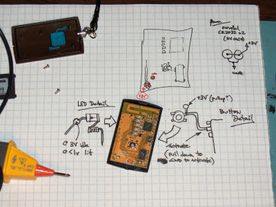
This wireless detector project allows you to sense the presence and relative signal strength of wireless hotspots. It is "always on" and communicates the presence and signal strength of an in-range hotspot by way of sequences of pulses - like a heartbeat you can feel. The stronger and faster the "heartbeat", the stronger the wireless signal detected.

This project consists of a microcontroller PIC 12F629, some custom interface electronics, a small vibe motor, and an off-the-shelf Wi-Fi detector from D-Link. The microcontroller periodically "presses" the button on the detector to initiate a reading. The microcontroller "reads" the output from the detector indicator LEDs and uses this as the basis for pulsing out a signal on the vibe motor, which the wearer can feel.

tag : wireless networks, hotspot detector, Wi-Fi strength signal indicator src

read more "Schematic PIC Wireless Networks Wifi (Hotspot) Detector"

Friday, October 8, 2010

Control :: What's Virtual PLC?

The commons PLC's (Programmable Logic Controllers) are micro controller circuits boards used for automation of industrial process...
read more "Control :: What's Virtual PLC?"

Tuesday, October 5, 2010

Schematic AVR Digital Clock with Roman Numerals


This digital clock project will display a Roman number instead Hindu-Arabic numeral system (1,2,3... ). The project uses micro ATTINY2313 as main processor and LCD to display the clock. When you turn on the device, it will shows a screen flashes "Tempera tempus" as reminder to adjust the time.


The adjustment is done via the small button.
  • Press and hold the button for about 3 seconds -> hours appear on the screen -> release the button.
  • Press the button again and hold -> the hours advance from "I" to "XXIV" -> release the button on the time right.
  • Wait about 3 seconds -> minutes to appear on the screen.
  • Press the button and hold -> the minutes advance from "nothing" to "LIX" -> release on just minutes.

    Unfortunately, you have to readjust the time after your turn off the power, because there is no RTC in this  project.

    Download schematic and source code here
    read more "Schematic AVR Digital Clock with Roman Numerals"