Friday, February 26, 2010

Schematic RC Pulse to PWM Converter Project

Microcontroller AVR - RC Pulse to PWM Converter Project
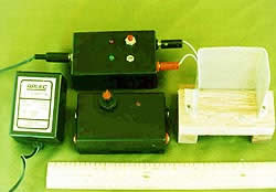
This Project describes an AVR chip and software that converts two easily formed R/C pulse signals and converts them into a PWM signal suit for driving small motors. This will be good solution for common problem for hobby robotics when controlling the drive level to a motor. As many hacked R/C servo's are used have poor control range. And many micro-controllers don't have built in PWM or the PWM is very slow and makes for lots of motor buzz.

The value of this AVR software application is that one can interface the output signals of the AVR chip to a wide variety of H-Bridge driver chips with a current capacity from 600ma to 5+ amps. Or, it could drive a discrete FET bridge for even higher capacities. The software runs on an Atmel AT90S1200 chip with a 16mhz clock. The project designe by Larry Barello.

Download :


User Guide (doc), schematic and source code

tag : RC, PWM, Converter, AVR project (src)


read more "Schematic RC Pulse to PWM Converter Project"

Wednesday, February 24, 2010

Pipe inspection robot 2

New Angle on Pipe Inspection

Pipelines are used extensively to carry natural gas to destinations
throughout the world. Large high-pressure transmission lines may
extend hundreds of miles cross country while smaller,
lower-pressure distribution lines are used to deliver gas to homes
and businesses. In the United States, there are more than
1.1 million miles of natural gas pipelines.
http://www.swri.org/3pubs/ttoday/Winter07/Pipelines.htm

Robot for Working in Small-Diameter Piping


TOKYO--Toshiba Corporation today announced that it has
developed the world's first miniature inspection robot able to
operate inside piping with a diameter as small as one inch (25mm).
The robot can undertake visual inspections and identify and
collect foreign objects. It is ideal for industrial applications in
such locations as electric power generation plants.
http://www.toshiba.co.jp/about/press/1997_02/pr2101.htm

A Hybrid Model-Based Vision System for Autonomous
Navigation of a Sewer Inspection Robot


The research project MAKRO is being conducted by four
partners from research and industry and aims at developing
an autonomous robot for surveying of modern concrete sewers.
The task of such a robot will be to collect a video record about
sewer conditions. The multi-segment robot consists of a mobile
base platform, and is equipped with a set of Sensors , a light
source, a laser crosshair projector and a camera, it must be
able to drive autonomously through a long system of sewer pipes.
An on-line Hybrid Model Vision-Based System has been
developed at GMD to navigate the MAKRO robot when it moves
along sewer pipes, approaches manhole junction areas, and
proceeds to enter the next pipe. The Vision System comprises
two different algorithms. The first one, called the orientation
algorithm, assesses the robot’s relative orientation with respect
to the pipe axis, in order to guide the robot through a pipe.
The second one, called the 3D interpretation algorithm,
recognizes the end of the current pipe at a manhole entrance
and locates the next pipe opening to move into when the
MAKRO robot is positioned before a manhole area of the sewer.
http://www.ercim.org/publication/Ercim_News/enw42/kolesnik.html

Pipe crawler - robots for video and laser inspection


These flexible robots are well suited for carrying out inspections
on pipe systems, especially those that have a lot of bends, vertical
sections and pipe branches.These robots are mainly used in the
nuclear power industry, refineries, chemical plants, petrochemical
plants, the offshore industry, gas pipelines, the beverage industry
and all types of pipe lines up to 500m long.Three drive elements
provide a speed of up to 200 m/h in both
horizontal and vertical directions and allow for effortless bend taking
http://www.inspector-systems.com/video_robots.html
read more "Pipe inspection robot 2"

Tuesday, February 23, 2010

Pipe inspection robot 1

HELI-PIPE
HELI-PIPE family consist of four different types of robots for in-pipe
inspection. The robots has two parts articulated with a universal joint.
One part (the stator) is guided along the pipe by a set of wheels
moving parallel to the axis of the pipe, while the other part (the rotor)
is forced to follow an helical motion thanks to tilted wheels rotating
about the axis of the pipe. A single motor (with gear reducer built-in)
is placed between the two bodies to produce the motion (no direct
actuated wheels). All the wheels are mounted on a suspension to
accommodate for changing tube diameter and curves in the pipe.
The robots are autonomous and carries their own batteries and
radio links.
http://www.ulb.ac.be/scmero/robotics.html#pipe2

Locomotion in tubes
Using a snake-like undulating travelling wave gait, the robot climbed
into and out of a 4" diameter ducting pipe. This was part of locomotion
through a general rubble pile of wooden pallets etc.
more

Pipe-Crawling Robot NC State Engineers
NC State Engineers Design Pipe-Crawling Robot to Save Lives


The most recent design, MOCASIn 2, is able to navigate
a complicated course of piping, complete with 90-degree turns
and vertical climbs. The segmented robot has the look of
a cyber-inchworm and uses pneumatics to force padded
"feet" against the pipe walls as it extends and contracts its
body along the pipe course.
"The use of pneumatics for movement is an important factor
because sometimes there are explosive gases present in buildings
that have collapsed," says Grant. "Electricity would have
the potential for igniting these gases so we designed the robot to
use compressed air instead. This gives it added portability, as well.
The robot can run off air tanks when there is no electricity to run
an air compressor, and it is designed so that it breaks down into
components that can easily be carried in backpacks to remote
disaster sites."
http://www.engr.ncsu.edu/news/news_articles/pipecrawler.html

Site Inspection of Gas Main by Helical Tomography


Invocon co-developed a system to inspect the internal and external
physical condition of subsurface pipe used for natural gas distribution.
Designed to measure the wall thickness of the pipe, the system
formulated a tomogram image of the cross-sectional area of the pipe.
http://www.invocon.com/tech/sight.html
read more "Pipe inspection robot 1"

Monday, February 22, 2010

Schematic LED Fader Project

Microcontroller - LED Fader Project
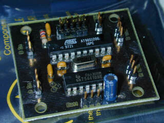
If you like make a LED project? LED Fader 2 could be interesting electronic project to build up. LED Fader 2 is a program that can control up to 16 outputs for driving LED's. All 16 outputs are pulse width modulated, giving 256 levels of brightness at a refresh rate of 100 Hz. A script language, designed for controlling the outputs, is provided as well. The program is written in AVR assembler for the AT Mega8 and Mega16 microcontrollers.


Download :

Source Code and Documentation

tag : LED, AVR Microcontroller Project (src)

read more "Schematic LED Fader Project"

Saturday, February 20, 2010

Current Controller DC Motor Driver


LMD18200
3A, 55V H-Bridge
General Description
The LMD18200 is a 3A H-Bridge designed for motion control
applications. The device is built using a multi-technology
process which combines bipolar and CMOS control circuitry
with DMOS power devices on the same monolithic structure.
Ideal for driving DC and stepper motors; the LMD18200
accommodates peak output currents up to 6A. An innovative
circuit which facilitates low-loss sensing of the output current
has been implemented.
Features
- Delivers up to 3A continuous output
- Operates at supply voltages up to 55V
- Low RDS(ON) typically 0.3Ω per switch
- TTL and CMOS compatible inputs
- No “shoot-through” current
- Thermal warning flag output at 145°C
- Thermal shutdown (outputs off) at 170°C
- Internal clamp diodes
- Shorted load protection
- Internal charge pump with external bootstrap capability

LMD18200 Datasheet Pdf
-
-
-
read more "Current Controller DC Motor Driver"

Thursday, February 18, 2010

Schematic Compact Variable Power Supply


This is a handy little power supply that can provide a voltage range of 1.25 to 13 volts and current up to 500 mA. The supply, created by Don Wilschefski, is housed in a small plastic enclosure 90 x 55 x 32 mm.

Download

schematic

search term : Power Supply, Handy supply, Variable PSU, analog project (src)

read more "Schematic Compact Variable Power Supply"

DC Motor Speed Control Circuit

Since the I.C. integrates a full H-Bridge in a single
package it is idealy suited for controlling DC motors.
When used for DC motor control it performs
the power stage required for both speed and direction
control. The device can be combined with
a current regulator like the L6506 to implement a
transconductance amplifier for speed control, as
shown in figure. In this particular configuration
only half of the L6506 is used and the other half
of the device may be used to control a second
motor
The L6506 senses the voltage across the sense
resistor RS to monitor the motor current: it compares
the sensed voltage both to control the
speed and during the brake of the motor.


L6203
DESCRIPTION
The I.C. is a full bridge driver for motor control applications
realized in Multipower-BCD technology
which combines isolated DMOS power transistors
with CMOS and Bipolar circuits on the same chip.
By using mixed technology it has been possible to
optimize the logic circuitry and the power stage to
achieve the best possible performance. The
DMOS output transistors can operate at supply
voltages up to 42V and efficiently at high switching
speeds. All the logic inputs are TTL, CMOS
and C compatible. Each channel (half-bridge) of
the device is controlled by a separate logic input,
while a common enable controls both channels.
The I.C. is mounted in three different packages.

Freture
- SUPPLY VOLTAGE UP TO 48V
- 5A MAX PEAK CURRENT (2A max. for L6201)
- TOTAL RMS CURRENT UP TO
- L6201: 1A; L6202: 1.5A; L6203/L6201PS: 4A
- RDS (ON) 0.3 (typical value at 25 C)
- CROSS CONDUCTION PROTECTION
- TTL COMPATIBLE DRIVE
- OPERATING FREQUENCY UP TO 100 KHz
- THERMAL SHUTDOWN
- INTERNAL LOGIC SUPPLY
- HIGH EFFICIENCY
read more "DC Motor Speed Control Circuit"

Tuesday, February 16, 2010

4A Full Bridge Motor Driver Circuit


L298
FULL-BRIDGE DRIVER
DESCRIPTION
The L298 is an integrated monolithic circuit in a 15-
lead Multiwatt and PowerSO20 packages. It is a
high voltage, high current dual full-bridge driver designed
to accept standard TTL logic levels and drive
inductive loads such as relays, solenoids, DC and
stepping motors. Two enable inputs are provided to
enable or disable the device independently of the input
signals. The emitters of the lower transistors of
each bridge are connected together and the corresponding
external terminal can be used for the connection
of an external sensing resistor. An additional
supply input is provided so that the logic works at a
lower voltage.

Feature
- OPERATING SUPPLY VOLTAGE UP TO 46 V
- TOTAL DC CURRENT UP TO 4 A
-LOW SATURATION VOLTAGE
- OVERTEMPERATURE PROTECTION
- LOGICAL "0" INPUT VOLTAGE UP TO 1.5 V
(HIGH NOISE IMMUNITY)
- Supply Voltage 50 V
- Logic Supply Voltage 7 V

read more "4A Full Bridge Motor Driver Circuit"

Sunday, February 14, 2010

Schematic Battery Charger for Hand Held Radio

Battery Charger for Hand Held Radio
This is a handy little charger that can provide a charging current of up to 120 mA continuously for batteries in the range up to 12 volts. This project inspired by 12 volt 500 mA plug pack at an amateur auction. Two potentially useful projects resulted from this plug pack. The other is a variable power supply. The supply is housed in a small plastic enclosure 90 x 55 x 32 mm.


Download :


Schematic

search term : Battery Charger, Hand held Radio charger, Analog Project (src )

read more "Schematic Battery Charger for Hand Held Radio"

2 Channel 600 mA Motor Driver Circuit


L293D
PUSH-PULL FOUR CHANNEL DRIVER WITH DIODES

DESCRIPTION
The Device is a monolithic integrated high voltage,
high current four channel driver designed to
accept standard DTL or TTL logic levels and drive
inductive loads (such as relays solenoides, DC
and stepping motors) and switching power transistors.
To simplify use as two bridges each pair of channels
is equipped with an enable input. A separate
supply input is provided for the logic, allowing operation
at a lower voltage and internal clamp diodes
are included.
This device is suitable for use in switching applications
at frequencies up to 5 kHz.

Feature
- 600mA OUTPUT CURRENT CAPABILITY PER CHANNEL
- 1.2A PEAK OUTPUT CURRENT (non repetitive) PER CHANNEL
- ENABLE FACILITY
- OVERTEMPERATURE PROTECTION
- LOGICAL "0" INPUT VOLTAGE UP TO 1.5 V (HIGH NOISE IMMUNITY)
- INTERNAL CLAMP DIODES
- Supply Voltage 36 V
- Logic Supply Voltage 36 V
read more "2 Channel 600 mA Motor Driver Circuit"

Friday, February 12, 2010

Beam Robot 3

B.E.A.M –bot

The trick is to design a circuit that detects whenever the capacitor
is fully charged. There are a lot of solutions that can be found on
the Internet. A nice idea is to use the voltage drop across a flicker
LED as it depends on the amount of background light. It's 2.4V
but slightly changes in darkness. The result is a creature which is
sensitive to light, at least that's the idea.
http://www.noortje.net/electronica/beam_EN.shtml

HRB-001 Micro BEAM Bot

This time I will be making a micro BEAM robot out of some junk
and a few components. BEAM stands for Biology, Electronics,
Aesthetics, and Mechanics. What differentiates BEAM robots from
the rest is the fact that BEAM robots do not rely on microcontrollers
or any type of programming to function. Instead of preprogrammed
digital logic they function by following the simple analog logic
of their components.
http://www.hyyppamedia.com/View/Projects/23

Build The Basic Robot

This style of robot is quite popular with BEAM builders, they are generally
only used as a proof of concept type build with the parts being scavenged
for other bots after a short time.
The reason that I decided to build one is because I want a robot base that
would make sensor such as encoding wheels unusable and force myself
to find some other way of accurate mapping. Why? because if you use
encoders, it only takes somebody to nudge the robot or for a wheel to slip
for the mapping to become unstable.
http://www.societyofrobots.com/member_tutorials/node/50
read more "Beam Robot 3"

Wednesday, February 10, 2010

Beam Robot 2

DIY Solar Robot Assembly

BEAM robotics basically starts from 3 philosophical tenets:
Use minimalist electronicsThis keeps complexity from “snowballing”,
and keeps costs downRecycle & reuse components out of technoscrap
This keeps things cheap, and avoids a lot of trips to parts stores;
virtually all the parts required to make a BEAM robot can be found
in broken electronics (ovens, walkman’s, CD players, VCRs, pagers…).
Solar power your critter if possibleWhile less powerful than even
a small battery (and, up-front, more
expensive), solar cell s last for years; solar-powered BEAMbots don’t
require constant battery replacements or down-time for battery
recharging. more

Beam Robot


analog electronics. It seemed that a PIC would work very well
for this kind of project. Very little extra circuitry is needed to
do both forword and backword walking sequences along with
a few other tricks.
http://mondo-technology.com/insect.html

Symet BEAM Robot


Symet is the first BEAM robot I ever completed, becoming active on
April 3, 2004. The idea and plans come from the book
Junkbots, Bugbots, & Bots on Wheels, by Dave Hrynkiw and
Mark W. Tilden. Its a solar powered robot that scoots along on
the tip of a single motor, using an FLED solarengine to store
and dump energy. When it hits an obstacle, it topples to
the side and, because of the orientation of the motor shaft,
it changes direction. No smarts, but lots of fun. I especially
enjoyed this guy because he was easy to get working, unlike
the other robot I tried to build first, but proved to be too
complicated for my first shot.
http://www.bufbotics.org/buf/symet/index.html
read more "Beam Robot 2"

Tuesday, February 9, 2010

Schematic PS to USB Joystick Converter

PS to USB Joystick Converter
If you have PS 1 or PS 2 joystick and you want use it for USB. Well this microcontroller project could resolve your problem now. PS2USB converts two Playstation 1 or Playstation 2 converter into usb josysticks. It also features the Dance Pad Code (Up+START+SELECT), so that it can be used in DDR games (tested with Stepmania). Works under Linux, Mac OSX, Windows. Take a look at another joystick project

note : no picture for the project, i just replace it with analog PS 1 joystick

Download :

source code and schematic

search term : PS to USB, Converter, Microcontroller Project (src)


read more "Schematic PS to USB Joystick Converter"

Monday, February 8, 2010

Beam Robot 1

The Incredible Walking Machine
This robot is a solar bicore walker that does not use a "solar
engine"
The circuit and motors are powered directly
from the 30 or so milliamps (in full sun) provided by a 37mm x 66mm
solar panel. On July 8, 2001 he took his first real world walks
showing the ability to walk over rough terrain including through
gravel, sand, dirt and some grass. WOW! With his feelers now
installed and his new wide traction rear legs, I am very
pleased with his overall performance.
more

Green Machine
AKA "My B.I.O.-BUG Hack"

The Plan: Rip the Hasbro toy bug guts out of a B.I.O.-Bug and turn
him into a true green BEAM machine. I want him to be solar
powered and able to walk continuously when in direct sun.
The circuits should be analog, BEAM, and as simple as possible
while still allowing robust enough behavior to give him
a chance for autonomous survival.
more

SunEater V


The SunEater_V behaviour is based on three rules:
-If no feeler switches are closed, the motors will obey the `eyes'.
SunEater_V moves towards the best light, while trying to avoid
shadow patches.
- If one of the feelers touches an obstacle, SunEater_V "follows
the wall" in the direction of the better light. Both this and the first
behaviour are illustrated
here. Thanks to the `mechanical memory'
- the robot keeps a feeler in contact with an obstacle during evasive
action - the motion remains deliberate, even if the voltage drops to
zero between steps.
- With both feeler switches closed, the robot will push
against one of them, trying to get free.
http://www.xs4all.nl/~sbolt/Other/suneaterV.html
-
-
-

read more "Beam Robot 1"

Wall-climbing Robot 4

RISE climbing Robots
Three RiSE platforms, with slightly elongated bodies to allow larger
integrated spiny+sticky feet (adapted from SpinyBot), were tested
on a variety of surfaces including, stucco, concrete with
pebbles, brick, plexiglass and trees.

more

Mecho-Gecko


While Full and Berkeley engineering professor Ron Fearing study
geckos' setae, the tiny hairs on its feet, for clues to replicating nature's
miraculous dry adhesive, iRobot has built two gecko-inspired robots
with Full's help. The Mecho-Gecko's three legs are tipped with
a pressure-sensitive adhesive (think Post-Its) to mimic the
unroll-and-peel-off manner in which geckos climb, while the Bull-Gecko
uses the same adhesive on bulldozer-like treads instead of legs.
The next design will be a legged version with a flexible spine.
read more "Wall-climbing Robot 4"

Saturday, February 6, 2010

Wall-climbing Robot 3

BIGGALO Wall Climbing Robot
BIGGALO (BIG uGly And LOud) is a pneumatics based robot that is
designed to climb relatively smooth vertical surfaces.
http://www.engr.uvic.ca/~pmauro/index.html

RIMINI
Development of New and Novel Low Cost Robot
Inspection Methods for In-Service Inspection of Nuclear
Installations


The robot uses a common principle to climb; which is to create
a negative force to stick the robot to the wall. This is achieved using
3 sliding suction cups, with the suction created by centrifugal pumps
driven by high speed air motors. The key advantage of this
technique is that expelling water creates a thrust force when the
system is not touching the wall. The force pushes the robot
towards the wall till the suction cup becomes attached to the wall.
http://www.twi.co.uk/content/rimini_final_paper.html

DynaClimber


Recent biological findings indicate that a number of fast climbing
animals (in particular the gecko and cockroach) climb in a dynamically
similar manner. Despite their different morphologies, limb number,
and attachment mechanisms both of these animals undulate laterally
with significant in pulling forces. These findings have prompted
a proposed template for dyanmic vertical climbing.
http://www.eng.fsu.edu/~clarkj/stride/climbing.htm
more
-
-
-
read more "Wall-climbing Robot 3"

Friday, February 5, 2010

Schematic AVR Remote control for TV (Salora)

AVR Remote control for TV

This is a AT90S2313 microcontroller project based which has function to turns ON the TV-channel 5 - at programmed time (triggered by alarm clock without buzzer). This electronic project use Infrared remote control with fixed code to turn on a TV Salora to a set timetable. The project designed by Emilio Pietro Giovanni.

Download

source code and schematic

search term : Remote Control, TV, AVR microcontroller project (src)


read more "Schematic AVR Remote control for TV (Salora)"

Thursday, February 4, 2010

Hexapod Robot

read more "Hexapod Robot"

Wall-climbing Robot 2

C-Bot Wall Climbing Bionic Robot

C-Bot Wall Climbing Bionic Robot By Niklas Galler
Do you ever imagine that someday, you can performs a wall
climbing with a help from robot or some device that can make you
stick to the wall. I never imagine that before. Maybe with the C-Bot
design by Niklas Galler we can start thinking to perform our own
“climbing stunt”. C-Bot a bionic wall climbing concept the
basically used the “gecko” innovative foot climbing design as
a template to climb wall without any artificial adhesion.


LARVA-I

We introduce a wall climbing robot system "LARVA" for visual
inspection of bridges using an impellent force adhesion method.
This adhesion mechanism consists of an impeller and flexible
suction seals which provide sufficient adhesion forces for supporting
its body on the surface by keeping the air pressure inside the foot of
the robot less than a critical safe value. A comprehensive study is
performed on the dynamic fluid modeling of the adhesion mechanism.
In addition, the stable locomotion on the vertical wall and an adhesion
control method for a wall climbing robot are derived. The controller,
though it is simple, provides a useful framework for controlling a wall
climbing robot.
http://mecha.skku.ac.kr/board/list.php?bbs_id=Robotics_02

MRWALLSPECT-III

RWALLSPECT III can walk in planes as well as climb walls
with suction pad. Since the robot is expected to be able to
move from wall to wall, wall to plane including negotiationing
convex or concave the robot. By performing intuitive and
geometrical analysis, critical aspects of design such as joint
ranges, design of ankles, and location of actuators are applied
to the robot. And also the robot is designed to carry an ultrasonic
NDT tool for inspection of the large suface of industrial utilities.
http://mecha.skku.ac.kr/board/list.php?bbs_id=Robotics_02
more
read more "Wall-climbing Robot 2"

Wednesday, February 3, 2010

Wall-climbing Robot 1

Electroadhesive Robots
Enabling wall-climbing robots for security/military,
inspection, and service applications
Electroadhesion offers advantages over other types of technologies
for wall climbing, including robust clamping over a variety of surfaces
(rough or smooth, conductive or insulating), low power, resistance
to dust, and fast, electrically controllable clamping and unclamping
. Thus, electroadhesion lends itself to a variety of wall-climbing
robots. Tracked "tank" type wall-climbing robots, as well as more
biomimetic inchworm-type robots, have been successfully
demonstrated to date using this technology. Other
advantages of electroadhesion include its non-damaging
nature, and lightweight, which is crucial in wall-climbing applications.
http://www.sri.com/rd/electroadhesion.html

NINJA-I, -II
Quadruped Wall Climbing Robot "NINJA-I, -II"


NINJA-I (1990-1993), NINJA-II (1994-). It is dangerous to inspect
and perform all the operations on the exterior walls of high rise
buildings and of the land bridges on high speed thoroughfares.
It also requires a great deal of expense in order to install the
needed scaffolding. NINJA is a wall climbing robot developed for
the purpose of automating this kind of operation. Units No. 1 and
2 of both have a height of nearly 1.8 m , a left/right width of
0.5 meters, a thickness of 0.4 meters, and a main body weight of
45 kg. All the legs of NINJA-I, as in Fig. 2, are driven by three
prismatic joint actuators in parallel mechanisms. They are oriented
to the direction of gravity as much as possible at all times, and
manifest th e effectiveness of "coupled drive (a drive method which
plans on making high output performance as a system by
cooperatively utilizing as much as possible all actuators that are
installed)". The feet are compliant to the wall surface while being
oriented at all times in the same direction as the body by a new
parallel movement mechanism which utilizes conduit wires.
The NINJA-II expands the reachable area of this foot mechanism
by inserting articulated joints.
more
Wall-Climbing Robot Spies at ICRA 2008

Stanford's Stickybot, a wall-climbing robot that uses
gecko-inspired directional adhesives on its feet. Photo:
Stanford University
more
-
-
-


read more "Wall-climbing Robot 1"

Monday, February 1, 2010

Schematic PIC MIDI expander with old ISA-BUS Soundcard

PIC project - MIDI expander
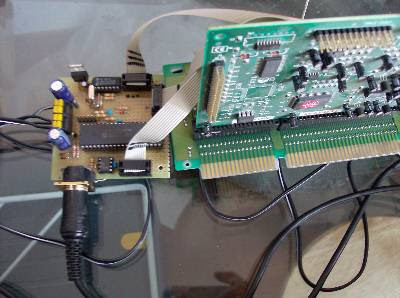
The circuit makes possible to realize a small MIDI expander using an old ISA-BUS soundcard. This microcontroller project based on micro PIC18F4320. Emilio, project designer, has tested on 2 different cards, and it should work for any card ADLIB OPL3 compatible (the I/O address MUST be 0x388).

The software responds to MIDI commands on Channel 1. The sounds are generated by the FM synthesizer built in the soundcard. The power is derived from two low-cost wall transformers (see picture) with variable output, set to 9V (the output is close to 12V).

Download :

Source code and schematic

search term : Midi expander, ISA BUS, Microcontroller PIC project (src)


read more "Schematic PIC MIDI expander with old ISA-BUS Soundcard"

Jumping Robot 2

Grasshoppper
Grasshoppper "robot" sets new high-jump record
While it doesn't exactly boast all that many robot-like characteristics,
this grasshopper-inspired bot from the Swiss Federal Institute of
Technology is apparently enough of one to lay claim to the robot
high-jump record, which it was able to capture handily by jumping
27 times its own height. That was done with the aid of a motor
originally designed to power the vibration unit of a pager which,
in this case, winds up two metal springs that eventually release
and spring the 5-centimeter tall bot into the air.
more

Jumping robot makes light work of stairs

Kim's team developed an ultra-lightweight version of an old technology:

the pneumatic ram. Powered by compressed air stored in two 2-litre
plastic bottles, the ram - an aluminium cylinder - is fired to launch
the robot to the required height.
To determine how much compressed air is needed for the jump,
an onboard processor first calculates how fast the robot is travelling,
using information from its 25-centimetre-diameter wheels. It also
works out the distance to the obstacle and its height, using
stereoscopic cameras and ultrasound Sensors . The processor
uses this information to calculate the jump, then sends a signal to
a solenoid valve that squirts high-pressure air into the ram for
the right length of time.
http://www.newscientist.com/article/mg19926666.400

“Jollbot” Jumping robots for space exploration

According to a team of engineers at the University of Bath, “jumping is
a good way to move over rough terrain, and is considerably easier to
design than walking.” PhysOrg.com reports that this is why they’ve
designed two jumping robots inspired by animals. They think that
their two new robots, Jollbot and Glumper, will help astronauts to during
future space missions. As one researcher said, “the cost per
kilogram of launching something into space is very large, so jumping
robots, which are likely to be light in weight to maximize
their own performance, are ideally suited from that perspective.”
Of course, such robots would also be useful to explore any
other places involving traversing rough terrains such as volcanoes.
http://blogs.zdnet.com/emergingtech/?p=626
read more "Jumping Robot 2"